



IntelliPaper
Abstract
In this paper, a new three-stage CMOS operational transconductance amplifier (OTA) for RTD applications is proposed. The presented structure eliminates the
feedforward path and strengthens the feedback path of compensation network together. In addition, the presented circuit uses only a small compensation capacitor on the order of 1 pF, which alleviates the chip area. The circuit is simulated using a 0.18-μm N-well CMOS technology process showing high performance and power efficiency regarding to figure of merit (FOM) factors defined in the literature. The frequency response of the proposed amplifier shows that the DC gain is about 120 dB and bandwidth is 18.8 MHz with a phase margin of 88° and power dissipation of 544 μW.
Explore Digital Article Text
I. INTRODUCTION
Process parameters in the industry or power plant have to be continuously monitored and controlled. Temperature is one of the most important parameters that must be controlled by the RTD, which is used to adjust the signal amplitude from the amplifier at the output of the Wheatstone bridge. Additionally, implementing an RTD of platinum is too expensive for the most applications. As a result, only small RTD elements are made out of platinum. To use the resistance value of RTD element, this resistance must be measured to the device. For this purpose, a copper wire with an insulating coating is used to connect the RTD element to the measuring device. The formation of platinum, copper also has electrical resistance. The resistance along the copper wire can affect the resistance value measured by the device connected to the RTD. In two-wire RTDs, there is no resistance to the copper wire to reduce the resistance and be measured against the copper wire. Consequently, two-wire RTDs are commonly used for approximate temperature measurement.
Three-wire RTDs are mostly used in industrial applications. These RTDs usually use the Wheatstone bridge measurement circuit to compensate the resistance of the copper wire. The response time of the temperature element is tested in all power plants and other industries. The transient response during the operation of the sensor is particular important to meet the requirements of the technical specifications and to enhance the signal range. An RTD is a transducer that converts temperature into an electrical signal.
If high energy is needed to move the drive unit, the controller command is amplified by the amplifier and then sent to the drive. Due to scaling down of channel length and power supply voltage, standard configurations such as cascode are not useful in OTA design based on CMOS technology, while multi-stage amplifiers can be used . However, by increasing the DC gain, such arrangements show low phase margin (PM) and high impedance nodes, which affect the frequency stability of the amplifier requiring the invention and use of techniques frequency compensation . In the case of a single-stage amplifier, one of the conventional frequency compensation methods that is specifically used is RNMC in which the first two stages must be negative. This technique is remarkable due to its design and without significant energy consumption. However, this method adds a zero frequency offset in the right half (RHP) to the amplifier, which causes stability problems . During the last year, several techniques such as current and voltage buffer , forward paths , AFFC and ACBC have been invented to solve that problem mentioned earlier, but they are not bound to achieve stability.
Moreover, the condition and improvement of gain bandwidth (GBW) did not succeed at the same time. This is due to the presence of RHP in the conversion function. In general, NMC and RNMC are two common methods for frequency compensation of three-layer OTAs. These two methods use two capacitors as a compensation network. In this paper, we present a new compensator method that uses a differential feedback path to remove the leading path and increase the frequency response to PM and GBW.
The frequency response analysis of the proposed circuit shows that the values of the compensating network elements can be controlled and adjusted for the phase margin and bandwidth. A detailed mathematical analysis of the proposed method is presented in the second part, along with operational theories, stability conditions, and design issues. The simulation results of the proposed topology and comparison among existing techniques are given in the third section. In the end, the conclusions will be presented in the last section.
II. RECOMMENDED TECHNIQUE
Figure 1 shows the structure of the proposed method. The output resistance and parasitic capacitor of each floor are specified by and respectively. is also a charge capacitor. In this structure, a differential feedback layer is used to achieve two goals. The first differential feedback layer forms the compensation network, and in the second layer, the output signal is driven from this layer, so it can reach the maximum DC gain. These two issues make the proposed method very effective to reach the desired GBW and PM. The proposed circuit is shown in Figure 1, where the compensation capacitor that has the Miller effect must be in the loop with a negative gain.
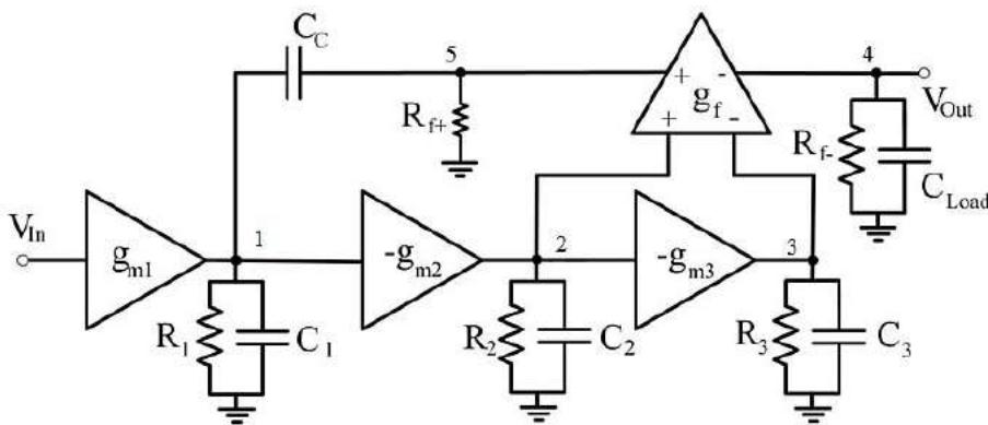 Figure 1: Structure of the proposed technique
According to the proposed structure in Figure 1, we can obtain the transformation function indicated in (1).
Note that the parasitic indices show that the capacitor and resistance are placed between the corresponding nodes and the ground. is the voltage of the node, and indicate the total capacity and total resistance of the ith node, respectively. In addition, shows the transmission conductivity of i-th layer.
III. CIRCUIT DESIGN
Figure 2 shows the transistor surface of the proposed circuit. The circuit includes a differential input stage, while the second and third stages include common source amplifiers. The fourth floor is another differential amplifier that forms the output floor.
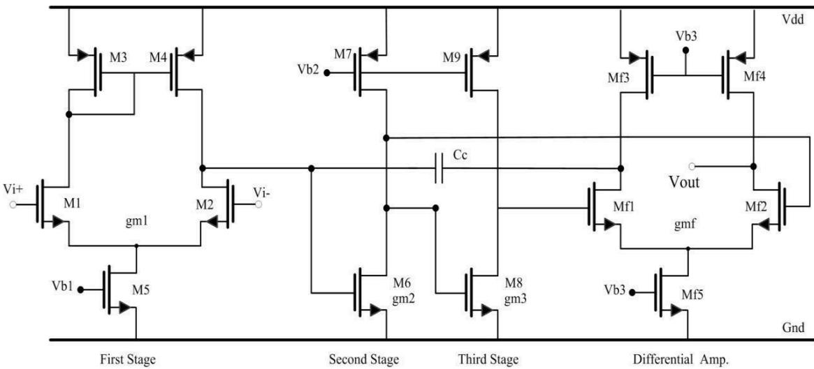 Figure 2: Transistor Level of the Proposed Technique
The input differential layer consists of transistors Ml-M5 with active load (M3, M4), while the second layer is a common source amplifier (M6) and current mirror M7, which form the transfer conduction gm1. The third layer (M8, M9) is the same as the previous layer, which form the transmission conduction . The output stage (Mf1-Mf5), which is driven by the third stage, is with gmf. The compensating capacitor (CC) from the output differential amplifier to the output of the first stage is located in the loop with negative feedback. Assuming , , and ignoring the dynamics of high frequencies and considering GBW is much larger compared to the poles of equation (1) and also considering that the gain of each floor is greater than unity, the conversion function The open loop of the amplifier (H2) will be simplified as equation (2).
As a result, the dominant and non-dominant poles as well as the zero of the transformation function are presented in (3), (4) and (5), respectively.
Additionally, closed loop transfer function with unit feedback gain is calculated as (6).
Figure 3 shows the frequency response of the proposed circuit. According to this figure, the simplified transformation function (5) follows the exact transformation function with appropriate accuracy. In fact, after removing the non-dominant coefficients, the simplified transformation function is obtained. These non-dominant coefficients usually appear due to
(6) the effects of parasitic capacitors. Therefore, another advantage of the presented method is that this compensation method is independent of parasitic capacitors and the estimated conversion function accurately leads to the improvement of the frequency response.
{"image_source":{"path":"images/01f3e210dfe833277427080151648d1fcf7c90b8b1bb4d6fea648f4f2f82ae06.jpg"},"content":"","chart_caption":[{"type":"text","content":"Figure 3: Frequency Response of the Proposed Circuit"}],"chart_footnote":[]}
IV. IMPLEMENTING OF THE PROPOSED CIRCUIT IN RTD APPLICATIONS
Most of the instruments and equipment used to control an industrial process are usually installed in the control room at a distance from the process; on the other hand, the measuring element is usually installed on the process or at a distance close to it. Therefore, the signal resulting from the measured quantity must be reliably sent to the control room, this is done by the transmitter. Figure 4 shows the transmitter connection to the monitor of the measuring device in various types of industrial equipment or process control.
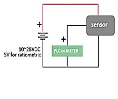 (b)
(b)
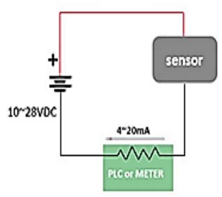 (a) Figure 4: Connecting the Transmitter to the PLC: a) Two-Wire Circuit, b) Three-Wire Circuit
Transducer output current is usually between 4 and 20 mA. By adding a resistive bridge to the inputs of the operational amplifier, the resulting circuit will be able to both add and subtract the voltage applied to the corresponding inputs. Figure 5 shows the completed proposed circuit.
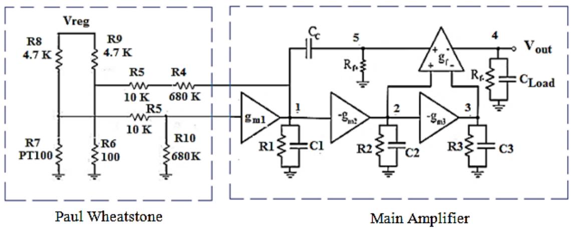 Figure 5: Proposed Test Circuit
This test is performed in power plants using a heating current of about 40 mA. To provide the necessary current for the test, the power supply is adjusted to the Wheatstone bridge, so the high current should be between 30 and 50 mA. The RTD is only stable up to 30 mA in one process. On the other hand, if the RTD is in a process that has large temperature fluctuations, a current higher than 50 mA is required to improve the signal-to-noise ratio (S/N). For this reason, an amplifier is used at the output of the Wheatstone bridge to enhance the signal amplitude. As a result, the output voltage of the Wheatstone bridge (V) changes linearly according to the RTD resistance ( ) during the test. Figure 6 shows the test response indicating that the transient response can be improved by using the proposed compensation technique.
{"image_source":{"path":"images/b4b48ee6b43f9c921023504d2d0bf756ba44f2e0fdc974183fe0fe742b084d16.jpg"},"content":"","chart_caption":[{"type":"text","content":"Figure 6: Output Time Response"}],"chart_footnote":[]} To compare the results with other compensation methods, we used the following two definitions of FOM (figure of merit) coefficients defined in [3].
The and indicate to improvement in small signal and large signal characteristics, respectively. Since in (6) and (7) the compensation capacitors are not included, we define a new FOM to consider their effects. Because the most of the chip area is consumed by passive elements [19] and the compensation capacitors are only passive elements in the OTA (through in many practical applications the output load is outside the chip), the new FOM is shown in (8). The performance comparison OTAs is summarized in Table 1.
Table 1: Performance Comparison of Different Topologies
| DC Gain ((dB) | Load (pF) | Power (μW) | GBW (MHz) | Compensation Capacitor ((pF) | Slew Rate (V/μS) | PM (°) | $FOM_s$ | $FOM_L$ | $FOM_{NEW}$ | |
| [NMC [13] | 100 | 100 | 345 | 0.22 | 110 | 0.25 | 68.3 | 0.06 | 0.07 | 0.054 |
| NMCNR [[2] | 100 | 100 | 345 | 0.32 | 78 | 0.30 | 70.5 | 0.09 | 0.08 | 0.115 |
| [DPZC [2] | 100 | 100 | 345 | 0.40 | 49.5 | 0.39 | 90.5 | 0.11 | 0.11 | 0.222 |
| [NGCC [12] | 100< | 100 | 365 | 0.25 | 96 | 0.33 | 69.1 | 0.06 | 0.09 | 0.062 |
| [NMCF [2] | 102 | 100 | 345 | 0.67 | 34 | 0.57 | 69.6 | 0.19 | 0.16 | 0.558 |
| NMCFNR [[2] | 100< | 100 | 345 | 0.80 | 28.7 | 0.63 | 72.1 | 0.23 | 0.18 | 0.801 |
| [DFCFC [10] | 100< | 100 | 372 | 0.96 | 35 | 0.80 | 66.6 | 0.25 | 0.23 | 0.714 |
| [AFFC [11] | 100< | 100 | 424 | 2.60 | 15 | 12 | 70.4 | 0.61 | 2.83 | 4.066 |
| [ACBC [9] | 100< | 100 | 365 | 2.06 | 18 | 1.22 | 69.6 | 0.56 | 0.33 | 3.111 |
| This work | 120 | 100 | 515 | 18.8 | 1.1 | 4.6 | 88 | 3.65 | 0.89 | 331 |
V. CONCLUSION
In this article, a new network compensation method has been presented to enhance frequency response of three-stage amplifiers for RTD applications. The proposed structure eliminates feedforward path and simultaneously strengthens the feedback path of compensation network while the Wheatstone bridge output voltage changes linearly according to RTD alters. The results prove the correctness of circuit theory analysis having superior performance with respect to small signal and large signal characteristics.
Conflict of Interest
The authors declare no conflict of interest.
Ethical Approval
Not applicable
Data Availability
The datasets used in this study are openly available at [repository link] and the source code is available on GitHub at [GitHub link].
Funding
This work did not receive any external funding.
References
Cite this article
Related Research



Special Issue
Launch a focused special issue to highlight research, emerging trends, and expert insights in your academic field.
