



IntelliPaper
Abstract
Here we trace the electrolytic deposition of copper and copper composites from a solution of the metal chloride salt in ethylene glycol / choline chloride based eutectics. This work also explores the use of the electrochemical quartz crystal microbalance (EQCM) to monitor both the deposition and the inclusion of inert particulates into the copper coatings. This technique allows the first in-situ the determination the thickness of coated copper beside particulate inclusion. However the composition of composite material was strongly dependant on the amount of species suspended in solution and the size of incorporated alumina particles. It was also revealed that the majority of material was dragged onto the surface that has been shown in the difference on thickness between copper coated with 50 nm and 1μ alumina.
Explore Digital Article Text
I. INTRODUCTION
Electroplating of copper is crucial for a variety of commercial and embellishing purposes including mega scale use in the electronics industry for production of printed circuit boards, selective case hardening of steel for engineering components and productions of electrotypes in printing industries. Copper may be easily deposited and electroplated with other metals and it is therefore particularly useful as a pre-coating for soft soldered work or for zinc alloy die-castings used by the automotive industry. In these cases the copper deposit provides a protective layer to the metal to allow further coatings to be applied . Also the incorporation of particulate material into metal coatings has become an area of technological interest; for example incorporation of poly(ethylene) can act as a corrosion barrier, incorporation of PTFE or mica can reduce surface friction whereas incorporation of alumina, silicon carbide, boron nitride or diamond can indeed enhance and improve the hardness property of the metal coating.
Commercial copper electroplating is based on aqueous solutions which have high solubility for electrolytes and metal salts resulting in highly conducting solutions. They have high throwing power and components with complex shape and internal surfaces can be plated with effortlessness. However, the cyanide and acid based copper plating solutions that are most generally employed are highly corrosive and suffer from several drawbacks including, toxic effluent, high energy consumption and air pollution. Recently, ionic liquids have been used as alternative plating solutions, and they have shown to be a less environmentally hazardous option. Copper has been electrodeposited from many ionic liquids in between the 1960s and 1970s, the study of these systems was dominated by the deposition of copper using chloroaluminate ionic liquids, some of which still remain popular. With the introduction of discrete anions such as , and ( in the 1990s copper could be more easily electrodeposited and the air and moisture stability of these systems made them a great technological improve. Endres and co-workers have shown that copper may be deposited from at various temperatures (BMP = butylmethyl pyrrolidinium). However, this particular ionic liquid has limited solubility for copper compounds and copper cations had to be introduced into the liquid via anodic dissolution of a copper electrode . This work highlights that a key issue with the design of ionic plating systems is the coordination chemistry and concentration of the metal complex. While ionic liquids with discrete anions show significant potential for the electrodeposition of electronegative metals such as aluminium , issues such as toxicity, availability and cost may limit their practical use. We have recently shown that simple eutectic-based ionic liquids can be produced using quaternary ammonium salts complexed with hydrogen bond donors such as acids, amides and alcohols. These
-
R.T. Carlin, H.C. De Long, J. Fuller and P.C. Trulove, J. Electrochem. Soc., 145, (1998), 1598.
-
B.J. Tierney, W.R. Pitner, J.A. Mitchell, C. L. Hussey and G.R. Stafford, J. Electrochem. Soc., (1998), 145, 3110.
-
C. Nanjundiah and R.A. Osteryoung, J. Electrochem. Soc., 130, (1983), 1312.
-
F. Endres and A. Schweizer, Phys. Chem. Chem. Phys., 2, (2000), 5455.
-
P.-Y. Chen and I.-W. Sun, Electrochim. Acta, 44, (1999), 441.
-
K. Murase, K. Nitta, T. Hirato and Y. Awakura, J. Appl. Electrochem., 31, (2001), 1089.
-
S. Zein El Abedin, A. Y. Saad, H. K. Farag, N. Borisenko, Q.
X. Liu and F. Endres, Electrochim. Acta, 52, (2007), 2746.
liquids, also known as deep eutectic solvents (DES) have been used for electropolishing , polymer synthesis , electroless (immersion) deposition and metal oxide processing. Most of our previous studies have concentrated on choline chloride as the quaternary ammonium salt as it is non-toxic, biodegradable and is used already as a common constituent of various household and industrial products. Hence it can be applied economically to large-scale processes. DESs formed with choline chloride and either urea or ethylene glycol have successfully been employed for the electrodeposition of zinc, tin, and zinc–tin alloys . It was shown that the choice of hydrogen bond donor affects the type of alloy and the electrochemistry of the components in solution, as well as the morphology of the coatings. The area of metal deposition using ionic liquids has been thoroughly reviewed in a series of recent articles and a book.
II. EXPERIMENTAL
Choline chloride (ChCl) (Aldrich 99%) was, when necessary, recrystallised from absolute ethanol, filtered and dried under vacuum. Ethylene glycol (EG) (Aldrich 99+%), was used as received. The mixtures were formed by stirring the two components together, in the stated proportions, at 50 °C until a homogeneous, colourless liquid formed. The liquids, once formulated, were kept in a thermostatic oven at 50 °C prior to use. Particulate suspensions were formed by mixing either (0.05μm or 1.0 μm, Aldrich), Aldrich) with the appropriate ionic liquid (1 ChCl: 2 EG, in wt./wt.% ratio.
Acoustic impedance electrochemical quartz crystal microbalance (EQCM) experiments were carried out using electrodes consisting of thin Au films (no Ti or Cr binding layer was used) evaporated on 10 MHz AT cut quartz crystals (International Crystal Manufacturing Co., Oklahoma City, USA); the surface finish of these crystals was unpolished. The piezoelectric active electrode area was 0.23 cm2. Crystal impedance spectra were recorded using either Hewlett Packard HP8751A network analyser, connected to a HP87512A transmission/reflection unit via 50 Ω coaxial cable (or an Agilent ENA E5061A network analyser) such that the centre of the spectrum was near the centre of resonance, (10 MHz), with a typical sweep width of 20-200 kHz depending on the interface. Peak frequency/mass, Q factor data were extracted from the acoustic impedance spectra by fitting to a Lorentzian line shape using methods described elsewhere.
{"image_source":{"path":"images/09695c25b948388557d63f8ba361e22e5ae5987a11655ef1124f4c0205ad4971.jpg"},"content":"","chart_caption":[],"chart_footnote":[]}
London Journal of Engineering Research
| (c) | 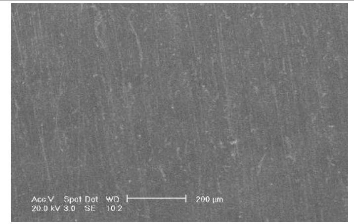 SEM Image for Unloaded Copper Deposits SEM Image for Unloaded Copper Deposits | (d)) | (f) Semi-Bright Deposit Obtained without Brighteners |
{"image_source":{"path":"images/e2d3d1318399dd2284e21d0817be53315ed1f4d43a409f0f36965f487d919514.jpg"},"content":"","chart_caption":[],"chart_footnote":[]} {"image_source":{"path":"images/6659a9f96bbedb9f9e8ad823719694c1350e9c08aea7dc1e862eb8c11be54fb9.jpg"},"content":"","chart_caption":[],"chart_footnote":[]}
{"image_source":{"path":"images/4928d0ebeac4e5c3fdb75d71cc2e6658473d29e638c18f9d486876158a0101f3.jpg"},"content":"","chart_caption":[],"chart_footnote":[]} {"image_source":{"path":"images/4ac8e471fe5e26685b59f41ac2fb5b4d668bb9d491c1db1e74369044e4a4923e.jpg"},"content":"","chart_caption":[{"type":"text","content":"(a)"}],"chart_footnote":[]}
{"image_source":{"path":"images/a6fac00608628d819bfd573eede2bec06db7570b5234afe901d43f0414e38d00.jpg"},"content":"","chart_caption":[{"type":"text","content":"(b)"}],"chart_footnote":[]}
 (c) Figure 2: Mass-Charge Plots for Copper Composite Deposition at -0.8 v and 0.02 M [CuCl2.2H2O] in 1 ChCl: 2 EG Based Liquid for Different Solution-Phase Loadings of 1 μM Al2O3 (e)
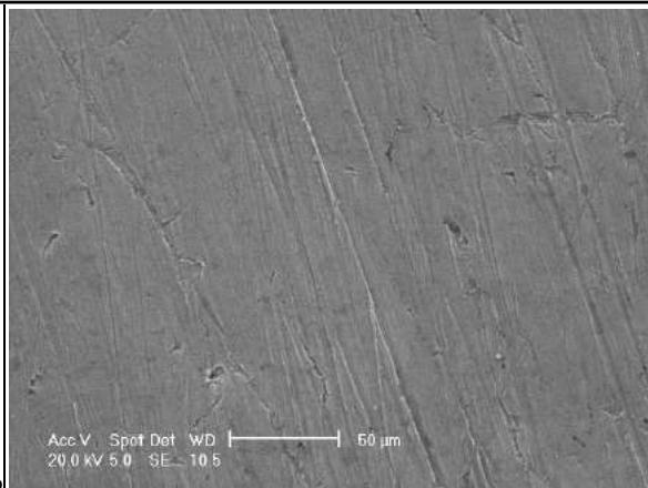
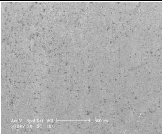 (d) (f) Figure 3: SEM Images of Copper Films Containing Dispersed Phase of Al2O3: Right 5% 1 μM Al2O3 - Lift 10% 1 μM Al2O3. Deposition at -0.8 v and 0.02 M [CuCl2.2H2O] in 1 ChCl: 2 EG Based liquid.(vertical Position)
III. RESULTS
Electrochemical quartz crystal microbalance experiments were used to obtain the mass/charge plots for copper deposition with two different sizes of alumna 50 nm and 1μm suspended in the ionic liquids. This technique utilises and permits real time in-situ in monitoring of both the copper deposition rate and the proportion of Al2O3 (or any particulate) incorporated into the composite. Since the particulate adds to the mass without consuming charge, where the place of AT cut working electrode was changed from horizontal to vertical position. This is important as it can address the issue of whether the composite material is settling on the surface or being dragged there by the copper complexes. The liquids were all kinetically stable on the time scale of the experiment i.e. the Al2O3 did not settle out at any time during the experiment, and this indicates that the sedimentation of the second phase is doubtful to be a crucial contributor to the overall rate of the material incorporation. Figure 1a depicts the mass-charge plot for copper at -0.8 V for different solution phase loadings of 0.05 μm Al2O3 in 1 ChCl: 2 EG based liquid (ethyline). Figure 2a shows the corresponding data for 1 μm Al2O3. The comparison between the mentioned figures that they are not quite similar as in the deposition of the copper codeposits, where the gold substrate is in horizontal location.27 By comparing between the alluded figures it has been observed that the mass of copper incorporated with the second phase sized 1μ m loaded is larger than the mass loaded with second phase 50 nm which is relatively interesting, moreover the deposition rates for similar experiments calculated from mass versus charge data is summarised in table1. The figures generally show that the codeposited copper with 1μ particle alumina is larger than the codeposed copper with 0.05μ particle alumina, it is a surprising results despite the 1 μm Al2O3 particles settle after about 24 hours whereas 0.05 μm particle suspensions are stable for over a week , also the rate of deposition by 5% micro particle is the highest, while the rate of deposition represented by 5% nano particles is lowest, this is needed to subject to further investigation. In the data shown in the table 1 the rate of copper deposition existence of 0.05 m alumina do not have a remarkable change despite SEM-EDAX images perceive even distribution of nano particles in the deposits . The rate of copper deposition incorporated with 1 alumina is increased from 0% to 5% second phase. This can be attributed to that the mean mechanism of inclusion dispersed phase is dragging instead of settling on the substrate. The inclusion of 10% 1 alumina shows its rate of deposition than the expected value, this could due to high concentration of alumina particles in the ionic liquid. Figure 1b and Figure 2 b represent the mass loaded against time, for the inclusion of 0.5% nano particles found to be the most loaded material, this could be attributed to the small amount of 0.05 m alumina is acting as micro stirrer . The thickness of both type of with codeposits nano and micro alumina viewed in Figure 1c and Figure 2c. The two Figures reveal that the thickness of copper codeposits is larger than the thickness of un loaded copper. The thickness of copper containing 1 m Al O particles almost the double the thickness of copper incorporated with 0.05 m Al O particles.
This is in a good agreement with the liquids were all kinetically stable on the time scale of the experiment i.e. the did not settle out at any time during the experiment and this suggests that the sedimentation of is unlikely to be a major contributor to the overall rate of material inclusion . The plot between the theoretical Q versus Q (data) is shown in Figure 1d and Figure 2d, where Q is the bandwidth and the resonant frequency determine the quality factor which can be in the mentioned Figures.
Table 1
| Cu deposits | Rate of deposits50 nm alumina ( $g/ cm^{2} C$ ) | Rate of deposits1μm alumina ( $g/ cm^{2} C$ ) |
| Unloaded | $9.0 x10^{-9}$ | $9.0 x10^{-9}$ |
| 0.5% | $8.3 x10^{-9}$ | $12.2 x10^{-9}$ |
| 5% | $7.0 x10^{-9}$ | $13.8 x10^{-9}$ |
| 10% | $8.3 x10^{-9}$ | $9.8 x10^{-9}$ |
The SEM images give a substantial effect of incorporating aluminium particles; nano and micro particles on the morphology of the deposits, the size and the quantity of alumina, this is consistent with results by codeposition of hard second phase of silicon carbide (45-55nm/1-3μ) and soft particles (PTFE) compared to deposition of pure copper, some mechanical properties such as hardness wear properties were studied . One advantage of ionic liquids listed above is the ability to deposit metals onto surfaces that normally inactive or are water sensitive. Figure 1 f shows a photograph of nickel sample which was coated directly in a similar manner to the copper samples. The image reveal Semi-bright deposit obtained without brighteners.
The EQCM studies indicate that the copper codeposits thickness with 1 micro alumina particles is double the thickness with the 50 nm alumina particle, which supports that particle codeposition is gravitationally independent.
IV. CONCLUSION
This work shows that ionic liquids, based on eutectic mixtures of choline chloride and hydrogen bond donors, such as ethylene glycol, can be used as electrochemical solvents for the electrodeposition of copper. The study revealed that in ionic liquid, the current efficiency for copper deposition is moderately efficient when AT cut working electrode is placed in a vertical position. Copper, incorporated with , has also been produced and shows that the loading of these species in the resulting electroplated films is not dependent on the concentration of particulate in a solution, when the working electrode is located horizontally. Gravitational settlement has been excluded as the main mechanism for particulate inclusion into the electrolytic deposits due to the position of the working electrode. It is surprising that the deposition copper incorporated nano particle alumina is fairly independent to the concentration of alumina, while the inclusion of micro alumina particles showed that 5% is the highest loading in the deposit, which is a very interesting observation.
Conflict of Interest
The authors declare no conflict of interest.
Ethical Approval
Not applicable
Data Availability
The datasets used in this study are openly available at [repository link] and the source code is available on GitHub at [GitHub link].
Funding
This work did not receive any external funding.
References
Cite this article
Related Research


Special Issue
Launch a focused special issue to highlight research, emerging trends, and expert insights in your academic field.
