

IntelliPaper
Abstract
The adiabatic gas expansion in the divergent rocket area generally results in the generation of thrust 19 required for propulsion by providing an environment where the gas molecules speed rapidly out the nozzle 20 exit after traversing the nozzle area. This study investigates the impact of wall grooving in the divergent 21 section of rocket nozzles on turbulence characteristics and flow performance using Computational Fluid 22 Dynamics (CFD). Employing the Finite Volume Method (FVM) and the k– ε turbulence model in 23 ANSYS Fluent, the study compares a conventional nozzle and a grooved counterpart under identical 24 boundary conditions. Key parameters analyzed include Turbulent Kinetic Energy (TKE), Turbulent 25 Eddy Dissipation (TED), and velocity profiles. Results reveal that while the grooved nozzle slightly 26 reduces axial velocity, it significantly enhances turbulence dissipation and flow stability by suppressing 27 lateral velocity fluctuations. Enhanced TED and uniform TKE distribution suggest improved mixing 28 and thermal energy control, making grooved nozzles a promising modification for advanced propulsion 29 systems.
Explore Digital Article Text
a Local speed of sound Stagnation (total) pressure P Static pressure Specific Heat Capacity of fluid h Enthalpy Mass flow rate of fluid mass Mean flow density Mean flow velocity Velocity Vector Flow velocity along upper wall boundary Flow velocity along bottom wall boundary l Periodic distance/lenght scale Constant relating to pressure L Lenght lateral velocity fluctuations. Enhanced TED and uniform TKE distribution suggest improved mixing and thermal energy control, making grooved nozzles a promising modification for advanced propulsion systems.
I. INTRODUCTION
The convergent-divergent nozzle is mainly responsible in governing the performance and efficiency of a rocket engine or other systems incorporating "De-Laval" nozzle designs. High-pressure, High temperature adiabatic expulsion of exhaust gases out the nozzle exit from the combustion chamber get converted into reduced-temperature, reduced-pressure and high kinetic energy leading to high thrust generation required for propulsion. One of the important factors influencing this phenomenon is turbulence which significantly affects the characteristics of the fluid flow through the nozzle especially within the expansion region of the nozzle. Performance could either be impacted either positively or negatively by the phenomenon of turbulence depending on its management.
in viscous energy dissipation from the random, chaotic turbulence due to high speed flows [2].
The main goal in the design of rocket engines is to have the adiabatic expanding gases be as efficient as possible whiles decreasing losses stemming from the phenomenon of turbulence and subsequent flow separation. Turbulence could lead to the exacerbation of flow separation where the boundary layer moves away or separates from the nozzle wall especially in the divergent nozzle section. As a result of the latter, shock waves result leading to decreased thrust efficiency, presence of unsteady fluid flow and decreased rocket stability . This necessitates controlling or mitigating turbulence especially in this nozzle section in an attempt to obtain optimal performance in operational range.
The interaction that occurs between the walls and flow of fluid in a rocket engine, the evolution of exhaust gases, velocity and pressure gradients all lead to the phenomenon of turbulence. Complex turbulent structures such as eddies, vortices and shock waves are some of the results of supersonic high energy flows. These features critically impact the flow pressure distribution, transfer of thermal energy, momentum among other turbulence features which critically influence the nozzle efficiency and performance . Potential thrust loses not better controlled is capable of resulting
Exploration of various techniques by studies in order to manage the phenomenon of tolerance in rocket engines have looked at the surface modification of nozzle walls. While surface grooving has shown to enhance aerodynamic performance in the field of aerospace engineering and in the internal combustion engine, its influence in rocket engines is not widely hence beckons further studies . Grooving is also capable of influencing the intensity of turbulence either by enhancing or reducing some flow structures per their orientation or structure.
The study of the effect of wall surface modification on turbulence is made possible by the utilization of Computational Fluid Dynamics (CFD) Tool by solving the governing equations of fluid flow (Navier Stokes equations) and carrying out flow simulation which is capable of giving the behaviour and evolution of the fluid flow in the nozzle and over structures. Various turbulence models can be utilized such as , Reynolds Averaged navier-Stokes (RANS), Large eddy Simulation to mention but a few to capture the complex behaviour of turbulence phenomenon [5]. Advancement of CFD has made it an indispensable tool capable of modelling and simulating highly intricate fluid flow phenomena with high accuracy.
Research has shown that problems resulting from the evolution of turbulence in the expanding nozzle section can be decreased through the redesigning of the surface wall boundary of the nozzle. For example, shown that the variation in the geometry of the nozzle such as the incorporation of nozzle ramps and contours are capable of reducing the boundary flow separation and hence bringing about stability in the flow by reducing the turbulence. In the same analogy grooving nozzle surfaces has the potential to reduce the commencement of the separation of the boundary layer resulting to a more efficient nozzle fluid flow. Further investigation is however required on the effects on overall thrust efficiency and thermal heat transfer.
To add to the effects of flow separation, turbulence also has a critical role playing in the thermal heat properties and management of rocket engines. Due to the increased energetic turbulent flows, the rate of convective thermal transfer which can lead to elevated temperatures around the region of occurrence. This elevation in thermal load can result in increased material failure or degradation and hence the need for turbulence regulation and as such thermal heat management. [6] mentioned that there was a need to check the heat transfer since it plays a crucial role not only in performance optimization, but also in maintaining the structural integrity of the nozzle and rocket as a whole from increased thermal stresses.
This study aims to assess the effects divergent grooving has on the flow turbulence of a rocket utilizing Computational fluid Dynamics analysis. By comparing conventional (ungrooved) and grooved nozzle designs, insights into varying nozzle turbulent flow performance can be assessed.
Comprehending the effects of turbulence within a rocket nozzle plays a very critical in engine performance and as such further study and research is required to be able to utilise how surface modification can be exploited in improving the output rocket performance. This study hence seeks to also contribute to growing data and knowledge on how a rocket engine performs through the use of Computational Fluid Dynamics techniques.
II. REVIEW OF LITERATURE
Turbulence creates complex and chaotic flow characteristics and patterns which tend to make it into quiet a challenging phenomenon to study. [2] mentioned that eddies and vortices are capable of bringing about viscous dissipation of energy within the fluid resulting in reduced efficiency if not mitigated adequately.
A phenomenon intimately related to turbulence is Flow separation which is very critical in rocket nozzle design and performance. The detachment of the flow boundary layer from the nozzle wall results in unsteady flow behaviour and subsequent decrease and degradation in thrust. Turbulence and flow separation are major concerns in supersonic nozzle flows. When boundary layers detach under adverse pressure gradients, shock structures and unsteady flow can degrade thrust and nozzle efficiency .
Surface grooves have shown promise in delaying flow separation and enhancing wall-bound turbulence dissipation in turbomachinery and aerodynamic applications . However, their effect in high-speed rocket nozzle flow—especially on turbulence kinetic energy (TKE) and eddy dissipation (TED)—remains largely unexplored.
CFD studies have shown that nozzle shape and wall modifications can significantly affect internal flow structures and turbulence–shock interactions [9;10]. Groove-enhanced designs may promote mixing, suppress unsteady shocks, and control wall heat transfer—all desirable for propulsion applications.
This study aims to extend these findings by applying the k- model in ANSYS Fluent to compare grooved and conventional nozzles under identical flow conditions, evaluating the effect on turbulence parameters and flow stability.
III. METHODOLOGY
3.1 Governing Equations and Conditions of Flow
At high velocities within a nozzle on channel, turbulence tends to manifest especially when flow encounters wall structure geometries and hence making the nature of structural geometries playing a critical role in turbulent phenomena. The aim here is to simulate turbulence within a conventional and grooved rocket engine using model which is composed of a two transport equations: Kinetic energy (K) and turbulent dissipation rate ( ) in CFD (Analysis System) which is capable of turbulent flow characteristics capturing through the nozzle.
3.2 Computational Domain and Meshing
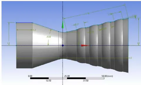
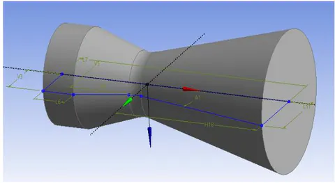
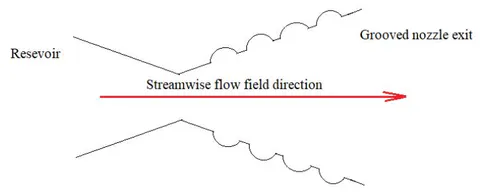
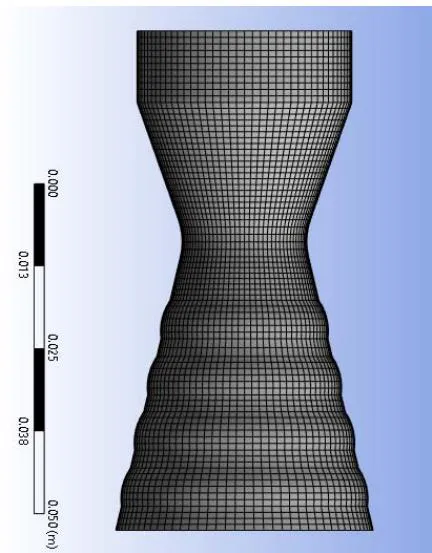
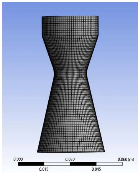
The Ansys Design modeler was utilized in capturing the dimensions) of both Conventional and Grooved convergent-Divergent rocket nozzles as shown in Figures 1 and 2 with the respective dimension given in Table 1. The symmetry of the rocket nozzle was conical and simulation of 2D axial flow domains. The latter leads to reduced computational power usage and the number of meshing elements required. The meshing and the domain (adiabatic) under computational consideration are shown in Fig. 4 and 5. The fundamental nozzle dimensional considerations are the combustion chamber, converging nozzle and the throat diameter linking the divergent nozzle section. These dimensions are provided in Table 1. The grooved nozzle geometry has four circumferential grooves along the wall of the divergent nozzle. The flow velocity is considered zero radially and hence perpendicular flow towards the walls are assumed no-slip. High resolution, structured and double precision mesh was generated to adequately capture turbulence effects over grooved regions along the nozzle wall. The resulting mesh obtained are seen in Figures 2 and 4. The boundary conditions for the flow inlet, outlet and wall along with the respective pressures as given in Tables 2, 3 and 4.
| Nozzle Section | Grooved Nozzle Dimension, mm | Conventional Nozzle Dimension, mm |
| Convergent Nozzle Angle, A10 | ||
| Divergent Nozzle Angle, A32 | ||
| Combustion Chamber lenght, L2 | 10.829 | 10.829 |
| Combustion Chamber width, L3 | 16.244 | 16.244 |
| Rocket Engine Length, L5 | 75.000 | 75.000 |
| Divergent Nozzle Axial lenght, L18 | 42.554 | 42.554 |
| Nozzle Exist Radius, L6 | 19.474 | 19.474 |
| Throat radius, L7 | 9.4303 | 9.430 |
| Groove width, L19 = L26 = L27 = L29 | 5.9763 | 0.000 |
| Groove depth | 0.55991 | 0.000 |
3.3 Selection of k-ε Turbulence Model
The Standard model is chosen with the CFD solver which solves the kinetic energy (k) and its accompanying dissipation rate ( ) along with the model constants
3.4 Solver Settings
A Solver based on density and suitable for high-speed compressible fluid flow capturing is utilized. Steady state time is set for the steady simulation of rocket nozzle flow.
3.5 Turbulence Modeling
Enhanced wall function or scalable wall function is selected for the implementation of wall treatment which also depends on the resolution of the mesh near the wall boundaries.
3.6 Residual Plots
These were important in identifying the nature of the computational solution based on iteration. The local imbalances of conserved variables present in each respective control volume are measured by the residuals. The solver used for this study is Analysis System Fluent and it solves the modified governing flow equations due to wall modification and boundary conditions.
IV. RESULT GENERATION
Convergence is arrived at the end of the iterative solutions. The respective plots and data contours are obtained describing the flow velocity and turbulence through the Convergent-Divergent rocket nozzles.
4.1 Analysis Procedure and Boundary Conditions
| Procedure | Setup |
| Problem Setup: General-Solver | Type: Density based |
| Models | Energy:On |
| Materials | fluid: Air( ) |
| Boundary Conditions | Inlet: Pressure Inlet, Gauge Total Pressure (Pa):, Outlet: Pressure Outlet, Gauge Pressure |
| Reference Values | Compute from: Inlet, Reference Zone: Solid body surface |
| Monitors | Create walls, Print to console and plot |
| Initialization | Standard initialization, Compute from inlet |
| Solution | Solution controls- Courant number= 5, Run calculation: Enter iteration number and initiate. |
| Boundary | Type |
| Inlet | Gauge Total Pressure 90[kPa] |
| Static Temperature | 288.1K |
| Outlet | Gauge Pressure |
| Wall | wall Function |
| Surface | Interior Surface |
| Quantity | Description |
| Material | Air at |
| Option | Pure substance |
| Thermodynamic State | Gas |
| Density | |
| Molar Mass | |
| Specific Heat Capacity | |
| Reference fluid Temperature | 25 C |
| Thermal Conductivity | |
| Thermal Expansivity |
4.2 Mathematical Formulations
4.2.1 Conservation of Mass
This is also often referred to as the "Continuity Equation". It states that mass in a system cannot be created nor destroyed but can only move from one place to the other. Having a control volume and applying the Gauss's divergence theorem in integral form, Eq. 4.1 is obtained representing the continuity equation [11].
stand for the control volume, density and the divergence of vector with u, v, and w are the velocity components in the i, j and k directions.
4.2.2 Boundary Conditions
{"algorithm_caption":[],"algorithm_content":[{"type":"text","content":"- Inlet\n "},{"type":"equation_inline","content":"u = 1, v = 0"},{"type":"text","content":"\n- Outlet\n "},{"type":"equation_inline","content":" = 0"},{"type":"equation_inline","content":" = 0"}]}
No-Slip and isothermal boundary conditions (u=v=o; )
Reference frame = Absolute Gauge total pressure = 101325 Pa Supersonic/Initial gauge pressure = 100000 Pa Temperature = 300 K
Reference Values
Density = 1.165636 kg/m Enthalpy = 301020 J/kg Ratio of Specific heat = 1.4 From the Continuity equation in divergence form below, a fluid particle moving from left to right under the due to pressure gradient within the fluid stream in order to satisfy the law of the conservation of mass, diverges whenever it impacts a bod, reconstitutes behind the body and hence maintaining the total fluid mass at the right side of the fluid path. The above statement is represented by the equation below:
The fluid velocity vector, for flow in two-dimensions and x and y are the streamwise and normal coordinates respectively.
Bounding the fluid flow field equations are two non-permeating and non-slip boundaries/wall identical in shape and area represented by
where is the velocity experienced by the upper wall boundary and is the velocity of the lower boundary. Beyond the upper and lower walls or boundaries, it is assumed that flow is zero for normal flow through a duct as seen below.
and stands for the upper and lower wall shape of the convergent divergent nozzle shape.
4.2.3 Periodic Conditionality of Flow Through Repeating Grooves
4.2.3.1 Wall Condition
With regards to the flow through a hollow duct with periodically repeating structures or grooves, the mathematically repeating or changing cross-sectional area is represented as below .
l, x and are the period of change which is a characteristic dimension, horizontal positions present within the grooves.
4.2.3.2 Evolution of Fluid Flow Cyclic/Periodic Velocity, Pressure and Temperature
Let the two-dimensional flow velocity be and .
4.2.3.3 Governing Flow Equations and Boundary Condition
The fundamental governing equations of flow are the Navier-Stokes equations and when incorporated with the periodic fully developed flow and the heat transfer equation:
4.2.3.4 Mass Conservation Equation
4.2.3.5 Momentum Equation
Where , and are the reduced pressure due to flow over grooves, fluid density and dynamic flow viscosity respectively. the modified pressure and actual flow pressure is given by [14].
and stands for the linear constant for pressure for a definite mass flow rate and the actual or corrected pressure respectively.
The above relation in Eq. (4.10) shows that the flow pressure decreases axially along the nozzle with each successive groove presence or occurrence. This differential pressure also accounts for the fluid mass flow from right to left of the flow wall boundary along the horizontal x-direction.
4.3 Governing Equation For Turbulent Flow
The component of the transport equation coupled with the compressible turbulence flow field equation are:
4.3.1 Continuity Equation
4.4.1 Turbulence kinetic Energy
4.3.1 Mass Transport
where standing for the type of fluid component, air.
Above equation is eddy viscosity based with being the modified pressure.
4.4 Two-Equation Turbulence Models: k-ε of RANS
[13] proposed a computational fluid dynamics two-part equation Eq. (4.14) and (4.15) to help account and describe the turbulence in a fluid flow. These are the Turbulence Kinetic Energy (TKE) and the Turbulence Dissipation Rate (TDR) or the Turbulence Eddy Dissipation (TED).
Production of turbulence kinetic energy (TKE)due to mean velocity shear
Production of TKE due to buoyancy
User defined source, Turbulence Prandtl number for k.
turbulence models
V. EVOLUTION OF TURBULENCE WITHIN A CONVERGENT-DIVERGENT NOZZLE
High Kinetic energy gas entities are generated in a rocket nozzle when high pressure and high temperature gases undergo rapid expansion {"image_source":{"path":"images/e7fda9c1eaf6a534a4e8907c2d6b79c81861899e0bd70064f32d2bc2d104eb38.jpg"},"content":"","chart_caption":[{"type":"text","content":"Figure 6: Turbulence Kinetic Energy versus Turbulence Eddy Dissipation"}],"chart_footnote":[]}
It is depicted in a comparison plot in Figure 7 that both conventional and grooved rocket nozzles have similar axial-velocity flow pattern but this is observed to change streamwisely after the nozzle-throat area some velocity perturbation is noticed for both nozzle with that of the grooved nozzle experiencing major velocity change but finally increasing. The major deferring flow feature is observed to occur about a fourth (1/4) of the axial distance aft the exit nozzle area.
Figures 8 and 9 show the behaviour of TED and TKE respectively for both conventional and grooved nozzles axially in their respective nozzles. In both figures, there is a direct performance correlation for both TKE and TED suggesting that irrespective of the nozzle type, both TKE and TED will be directly proportional. In Figure 8, TED for both nozzle types have relatively wide range whereas looking at TKE for both nozzles, the adiabatically. It is assumed that all thermal energy is used to propel the molecular gaseous species. Figure 6 shows a directly proportional relationship existing between TKE and TED in a nozzle with grooves. As flow speeds towards the exit nozzle area where the presence of wall structural geometries are dominant, there is an increased "fluid-structure" interaction leading to increased TKE and its subsequent dissipation (TED).
{"image_source":{"path":"images/6871c77baeb76728d0b7d6bf12e7a1c1cc98d6c16e7f4e64d1fd234dad6f6d75.jpg"},"content":"","chart_caption":[{"type":"text","content":"Figure 7: Comparative axial velocities for conventional and grooved nozzles"}],"chart_footnote":[]} range much closer but for the combustion chamber and towards the exit nozzle area.
{"image_source":{"path":"images/6419227b9a6786c1de2d34b40bd09722a385b39190a381ebb6602cb1e7336cfd.jpg"},"content":"","chart_caption":[{"type":"text","content":"Figure 8: Axial comparison between conventional(ungrooved) and grooved nozzle Turbulence Eddy Dissipation"}],"chart_footnote":[]} In Figures 10 and 11, the effect of velocity on turbulence on a conventional and grooved convergent-divergent nozzle geometries is presented. Figure 10 shows the effect of TED for both nozzle geometries where it is seen that the general rate of occurrence is relatively wide but tapers to as both increase gradually with increase in axial velocity with some perturbation between 550m/s to 600m/s. In the case of the effect of axial-velocity on TKE from Figure 11, the rate range of occurrence is much closer as compared to that of TED, there is also a gradual increase with increase in velocity but perturbation only begins to manifest when velocity is nearly 600m/s.
{"image_source":{"path":"images/c2c09d1cacf37105c1a3af8d2f9c8ca99d5a4ce8ba72f446cc1ff75ddea19655.jpg"},"content":"","chart_caption":[{"type":"text","content":"Figure 10: Comparison of the effect of velocity on Turbulence Eddy Dissipation for conventional(ungrooved) and grooved Nozzles"}],"chart_footnote":[]} {"image_source":{"path":"images/ec3f3850da53b685eeeb83c07e9717c794fe76d1229a1ad167e974d868b832c1.jpg"},"content":"","chart_caption":[{"type":"text","content":"Figure 12: Grooved nozzle velocity contours"}],"chart_footnote":[]}
{"image_source":{"path":"images/f9901bc155f3a7d59084b4ce2e8b0b1a79db37a283246a839387c633d8256c3d.jpg"},"content":"","chart_caption":[{"type":"text","content":"Figure 9: Axial comparison between conventional(ungrooved) and grooved nozzle Turbulence Kinetic Energy"}],"chart_footnote":[]} {"image_source":{"path":"images/120cd5bb3c1237d21e4c3fe536386c1f9afa1a7a150e755f064c4853f595456b.jpg"},"content":"","chart_caption":[],"chart_footnote":[]}
{"image_source":{"path":"images/1bf0d7a6da9da268247748ad7444989480004561c710ddbfdf904378f70af0e3.jpg"},"content":"","chart_caption":[{"type":"text","content":"Figure 11: Comparison of the effect of velocity on Turbulence Kinetic Energy for conventional(ungrooved) and grooved nozzles"},{"type":"text","content":"Figure 13: Conventional nozzle velocity contours"},{"type":"text","content":"CFD Investigation of Turbulence Behaviour in Grooved Divergent Rocket Nozzles using the k-ε Model"}],"chart_footnote":[]}
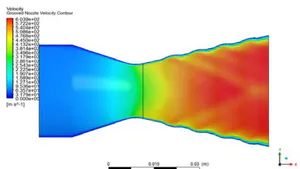
Figures (12 and 13) show the contours of velocity increasing axially within the nozzles of the grooved and conventional nozzle geometries respectively. However, it is further observed in Figure 12 that, due to the grooves on the wall surface of the grooved nozzle, there is the {"image_source":{"path":"images/715853b29a517fdf471bfdaeba6da016e9f3faf576d1f07dd010edd9b0f8b938.jpg"},"content":"","chart_caption":[{"type":"text","content":"Figure 14: Contours of grooved nozzle Turbulence Kinetic Energy"}],"chart_footnote":[]}
Figures 14 and 15 show the TKE contours occurring within the grooved and conventional nozzles respectively and it is observed that, TKE for the grooved nozzle is much more pronounced with a maximum energy to represented a orange contour between the last nozzle groove and the nozzle exit area. The energy range present within the grooved nozzle was between to . Present in the {"image_source":{"path":"images/4cea80b22cf948bdee003c2c0f0647b74a67077c33a4fceb54797eb01fb35269.jpg"},"content":"","chart_caption":[{"type":"text","content":"Figure 16: Contours of grooved nozzle Turbulence Eddy Dissipation"}],"chart_footnote":[]}
Figures 16 and 17 are depictions of the contours for the TED in occurring within the grooved and conventional nozzle area geometries. The dissipation energy observed in the grooved nozzle was between to with the formation of backward facing patterns which are absent in the conventional nozzle. The "diamond" patterns can be attributed to the interaction between the geometry of the groove and the gas flow within and out of them.
{"image_source":{"path":"images/50b7bae3921a786a93a84709051cc570de1b11db833683b67162f60f7fce85ad.jpg"},"content":"","chart_caption":[{"type":"text","content":"Figure 15: Contours of conventional nozzle Turbulence Eddy Dissipation"}],"chart_footnote":[]} conventional nozzle was an energy range between 5.829 * 10 to 3.272 * with a greater energy seen around the region nearest to the divergent nozzle area. It is how ever noticed that, the commencement of TKE was delayed within the grooved nozzle whiles within the conventional nozzle, the occurrence of TKE was much more pronounced immediately aft the nozzle throat area.
{"image_source":{"path":"images/5970e6b441f94dae662716ae0cb6b79bb9374def1051d96c2d77fc9894575f32.jpg"},"content":"","chart_caption":[{"type":"text","content":"Figure 17: Contours of conventional nozzle Turbulence Eddy Dissipation"}],"chart_footnote":[{"type":"text","content":"greater part dominant around the latter nozzle exit wall area."}]}
| Parameter | Min (Conv.) | Max (Conv.) | Min-Max (Grooved) | Comments |
| U-Vel ( ) | 146 | 2070 | 152-1650 | Reduced maximum axial velocity ensures smoother flow acceleration and minimizes shock formation risks. |
| V-Vel ( ) | 616 | 638 | 382-385 | Narrower lateral velocity range indicates improved flow stability and reduced side thrust forces. |
| TKE ( ) | 3.910 | 33400 | 22.3-22100 | Higher minimum and lower peak TKE promotes efficient, stable turbulence without energy waste. |
| TED ( ) | 14400 | 164000 | 272000-449000 | Lower TED peak values ensure more uniform energy dissipation and smoother combustion stability. |
In Table 5 are the minimum and maximum Variable Range summary values for the velocity, TKE and TED respectively. It is observed that, The grooved nozzle has a lower maximum TKE and a greater maximum TED respectively. A higher TED denotes that the system is capable of dissipation TKE as they form or occur as Compared to that of their ungrooved or conventional counterpart. U-velocity for the conventional nozzle showed lower minimum and maximum velocities as compared with that of the grooved nozzle, however the V-velocities for the conventional nozzle showed higher values as compared with the grooved V-velocity values.
U-Velocity (Axial): The grooved nozzle has a slightly lower maximum axial velocity compared to the conventional nozzle , indicating potential energy loss or flow resistance due to groove structures.
V-Velocity (Lateral): Grooved nozzles exhibit reduced lateral velocity fluctuations, with a smaller range than conventional nozzles. This suggests a more stable flow with less swirl or cross-stream mixing.
Turbulent Kinetic Energy (TKE): Although the maximum TKE in grooved nozzles is lower, the minimum is higher than in the conventional nozzle. This may reflect a more uniform but less intense turbulence field.
Turbulent Energy Dissipation (TED): The grooved nozzle shows higher minimum TED and lower maximum TED , indicating a more consistent rate of turbulence dissipation, which may enhance controlled mixing without extreme energy losses.
Overall Insight: Grooved nozzles provide a potentially more stable and uniform turbulent flow field, which could be beneficial in reducing flow separation or structural vibrations, albeit at the expense of slightly reduced flow velocities and turbulence intensities.
VI. TURBULENT KINETIC ENERGY (TKE)
| Source | TKE ( ) |
| Grooved Nozzle (Present Study) | 22.3 |
| Conventional Nozzle (Present Study) | 3.91 |
| [15] | 12.5 |
| [16] | 12.0 |
| [17] | 11.29 |
| [18] | 11.5 |
The grooved nozzle shows the highest TKE, indicating superior turbulence generation and energy transfer. From Table 6, TKE in the grooved nozzle is nearly double the highest reported in literature. This confirms the superior turbulence generation, which is essential for vortex breakup, flame holding, and improved heat transfer.
VII. TURBULENT DISSIPATION ENERGY (TDE)
| Source | TDE ( ) |
| Grooved Nozzle (Present Study) | 272000 |
| Conventional Nozzle (Present Study) | 14400 |
| [15] | 0.015 |
| [16] | 0.041 |
| [17] | 0.013 |
| [18] | 0.013 |
TDE for the grooved nozzle is significantly higher, ensuring effective breakdown of turbulent structures and uniform energy distribution. Table 7 hence shows that TDE from the grooved nozzle in orders of magnitude is higher than both conventional and prior studies. This indicates more energy is dissipated through turbulence, leading to efficient mixing and reduced coherent structures. It also enhances thermal energy distribution downstream.
7.1 Observed Improved Grooved Divergent Rocket Nozzle Performance
7.1.1 Enhanced Shear and Mixing (High TKE & v-Momentum)
The grooved nozzle shows a turbulent kinetic energy (TKE) of 22.3 , significantly greater than the conventional nozzle's TKE of 3.91 .
The v-momentum is 1442 kg·m/s compared to just 78 kg·m/s for the conventional nozzle.
These values indicate superior radial thrust and turbulence—critical for fuel-air mixing, energy distribution, and flame stability in combustion systems such as rocket engines.
7.1.2 Greater Energy Dissipation (TDE)
The grooved nozzle exhibits a total dissipation energy (TDE) of 272000 , much higher than the conventional nozzle's TDE of 14400 .
This higher dissipation helps reduce large turbulent structures, promoting finer-scale mixing and more efficient combustion.
7.1.3 Directionally Efficient Flow
Although the grooved nozzle has a lower v-velocity (383 m/s) compared to the conventional nozzle (616 m/s), it achieves higher directional control through greater radial momentum.
This suggests the grooved design effectively redirects flow energy into turbulence and mixing, rather than just raw lateral velocity.
7.1.4 Balanced Axial Velocity
The u-velocity for the grooved nozzle is 152 m/s, slightly higher than the conventional nozzle's 146 m/s.
This indicates no compromise in axial thrust while achieving significantly higher radial mixing and turbulence.
The grooved nozzle offers clear advantages in turbulent mixing, momentum control, and energy dissipation. These qualities are critical for applications requiring improved combustion efficiency, flame stability, and heat transfer performance. The performance metrics (TKE, TDE, v-momentum) make a compelling case for favoring the grooved nozzle design over conventional configurations since the grooved nozzle demonstrates superior performance in nearly all critical parameters when compared to the conventional nozzle and referenced studies. Its high TKE, exceptional radial momentum, and elevated TDE establish it as the most effective design for enhancing mixing, combustion stability, and thermal efficiency. Therefore, the grooved nozzle is highly recommended for advanced propulsion and energy systems.
VIII. CONCLUSION
The comparative CFD analysis of grooved and conventional rocket nozzles reveals that wall grooving has a profound effect on turbulent flow behavior. The grooved nozzle demonstrates enhanced turbulence energy dissipation and more uniform TKE distribution, resulting in better flow stability and reduced risk of flow separation. Although there is a modest reduction in maximum axial velocity, the overall aerodynamic performance benefits from improved radial mixing and momentum control. These findings underscore the potential of wall-surface modifications, particularly grooving, as an effective strategy for optimizing rocket nozzle performance in high-speed propulsion applications. Future work could explore groove pattern optimization and three-dimensional effects for further performance enhancement.
Limitations and Future Work
This study focuses on two-dimensional, steady-state simulations using the standard k-ε turbulence model. While informative, this approach may not capture three-dimensional or transient effects such as swirl or pulsation. Future research should include 3D simulations, alternative turbulence models (e.g., k-ω SST or LES), and experimental validation to further substantiate the findings.
Data Availability Statement: Data are contained within the article
Conflict of Interest
The authors declare no conflict of interest.
Ethical Approval
Not applicable
Data Availability
The datasets used in this study are openly available at [repository link] and the source code is available on GitHub at [GitHub link].
Funding
This work did not receive any external funding.
References
Cite this article
Related Research

Special Issue
Launch a focused special issue to highlight research, emerging trends, and expert insights in your academic field.