

IntelliPaper
Abstract
The power industries daily compensate for the rising demand for electric power globally by installing new transmission lines or efficiently operating the current ones, thus transmitting more electricity from one specific point to another. However, building new transmission lines is highly challenging due to the high cost and regulations. In addition, the flow of electricity is predominantly along an undesirable path, and its stability is always affected by voltage fluctuation in the transmission lines. An intelligent approach to mitigating this problem is to control the flow of electric power effectively and efficiently in the transmission line system. This work outlined the basic operational comparison concepts ofFlexible Alternating Current Transmission System (FACTS) devices of the Unified Power Flow Controller (UPFC)and the Distributed Power Flow Controller (DPFC) based on their respective active power exchange. The UPFC incorporates a common dc-link between its shunt and series converters. The DPFC operates without the common D.C-link, splitting the three-phase series converters into many single-phase series distributed converters via the transmission line. The operational comparison between UPFC and DPFCis modeled and simulated in Matlab/Simulink environment to illustrate their control capability in the flow of electric power. The simulation results show the performance enhancement reliability of the DPFCin improving the voltage stability and power transfer capability over the UPFC.
Explore Digital Article Text
I. INTRODUCTION
Recently, FACTS devices have attracted significant attention because they offer unique properties for regulating alternating current (A.C.) transmission, increasing or reducing the power flow in specific lines, and responding almost instantly to the stability crisis. The ever-growing demand for electrical power worldwide has necessitated transporting more electricity from the generating point to the end-users via interconnected transmission lines . However, the natural flow of electricity can result in the overloading or underloading of the transmission lines, affecting the stability and the controllability of power flow with increased variation in line voltage. The power flow control is challenging since the power system is highly complex, having hundreds of buses and transmission links. In addition, power systems comprising generators, transmission links, and power electronics-based FACTS devices are nonlinear and multivariable systems with active properties over various operating conditions .
In recent times, significant research studies have been undertaken to improve the control capability of the transmission interconnection system that supplies power from the generating point to the loads and minimizes operational and maintenance costs. The design of the internal controllers of FACTS devices is solely dependent on the traditional linear control methods of classic or Proportionate Integral (P.I.) controllers and other power flow control techniques of FACTS devices such as Static Synchronous Compensator (STATCOM), Static VAR Compensator (SVC), Static Series Synchronous Compensator (SSSC), and Gate Controlled Series Capacitors are not effective in providing the solution to the problem of nonlinear loads in power grids . Mitigating these undesirable conditions requires using FACTS devices of UPFC and DPFC. These FACTS devices operate in power system networks as electric power flow controllers for the system's parameters, such as line impedance, transmission angle, bus voltage, and components of active power and reactive power . The elimination of the common D.C-link and the splitting of the three-phase series converters into several single-phase series distributed converters via the transmission line make the DPFC provide better performance in controlling electric power flow than UPFC. This paper compares detailed analysis performance of FACTS devices of DPFC and UPFC in a Matlab/Simulink environment. This paper's work is structured as follows: Section II explains the FACTS devices of UPFC and DPFC basic concepts. In section III, comparisons between UPFC and DPFC are described. Section IV is the simulation results and discussions of the UPFC and DPFC. The final section states the paper's conclusions.
II. FACTS DEVICES OF UPFC AND DPFC BASIC CONCEPTS
2.1 UPFC Concept
The UPFC concept is one of the third generations in the FACTS family devices . The UPF controls voltage magnitude, phase angle, and active and reactive power flow via the transmission line. It also has the potential to control three parameters of line power flow, such as line impedance, voltage, and phase angle, simultaneously . This device also provides rapid reactive power compensation for high-voltage power transmission systems.
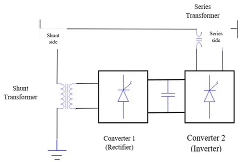
Fig. 1 shows converter 1 (rectifier) and converter 2 (inverter) with a common D.C. link. The UPFC controls the power system transmission line's active and reactive power flows via the series inverter by injecting a symmetrical three-phase voltage of controllable magnitude and phase angle [5]. The inverter operates to transfer the active power to the D.C. terminals. The shunt inverter uses the line D.C positive and negative power to keep the voltage across the storage capacitor constant, thus, making the total active power absorbed by the UPFC from the line equal to the inverters and their respective transformers losses.
Voltage regulation at the point of connection VDC is provided by using the remaining capacity of the shunt inverter to exchange reactive power with the line. The two voltage source inverters can work autonomously by separating the dc side. The shunt inverter operates as a STATCOM (Static
Synchronous Compensator) for generating or absorbing reactive power that regulates the voltage magnitude at the connection point.
Fig. 2 shows the shunt control block diagram in which the shunt controller in UPFC operates to charge the dc-link capacitor voltage that enhances the series converter for improved power flow control and maintaining voltage profile [6].
![Fig. 2: UPFC shunt control block diagram [6]](https://doc.journalspress.com/pnhb92_87887/ocr/images/derivatives/a0/a049a7bd6489ad89cc97849dc0623062011d72b9085074f0f6eff1dae436da65.webp)
Fig. 3 shows the block diagram of the series control where the series converter generates the real and reactive power at the transmission line using the dc-link capacitor voltage. This control strategy only takes two reference values of and and also compares and with to derive and [7] as expressed by equations (1-2)
![Fig. 3: UPFC series control block diagram [7]](https://doc.journalspress.com/pnhb92_87887/ocr/images/derivatives/34/343bcf281fcd3322491a68e483dd4273eae095121180121f3a373b3c57db8d62.webp)
2.2 DPFC Concepts
The Distributed Power Flow Controller (DPFC) is a new voltage and power stability enhancement concept developed from the UPFC . The DPFC operates without a common dc-link between the UPFC shunt and series converters.
However, it utilizes the distributed FACTS concept related to the UPFC, which involves splitting the three-phase series converter into several single-phase series distributed converters via the transmission lines . The DPFC compensates for real and reactive power flow using a shunt and many series-connected converters. In contrast, each converter operates autonomously, and their respective D.C. capacitors provide the needed D.C. voltage. The UPFC achieves its voltage stability enhancement and improvement of power (real and reactive power) transfer capability by the end-to-end connections of the shunt-series converters. In addition, the DPFC eliminates the D.C. link between the shunt-series converters to maintain the same control capability as the UPFC and presents the non-sinusoidal voltage and current as the expression of the sum of the sinusoidal components at different frequencies based on the Fourier analysis. The active power produced is due to the product of the voltage and current parameters. Because the integral of one or two terms with different frequencies is zero, resulting in the active power expression as in equation 1.
Equation (1) shows the active power at different frequencies is autonomous of each other, such that and represent the voltage and current of the harmonic frequency and is the angle between the voltage and current, leaving the converter with the possibility of absorbing the active power in one frequency and generating it in the other frequency. However, incorporating the DPFC into the transmission network can result in the shunt converter absorbing the active power at the fundamental frequency from the grid and injecting the current back into the grid at the harmonic frequency, thus, enhancing the flow of harmonic current via the transmission network.
Consequently, in a three-phase system, the third harmonic in each phase is equal and is referred to as the zero-sequence, where the shunt-series converters, high pass filter, and the ground form the closed loop for the harmonic current. In theory, the third, sixth, and ninth-harmonic frequencies enhance the active power exchange of the DPFC because they are all zero-sequence.
Grounding the star-delta transformer approach can be significant for routing the harmonic current in a meshed network.
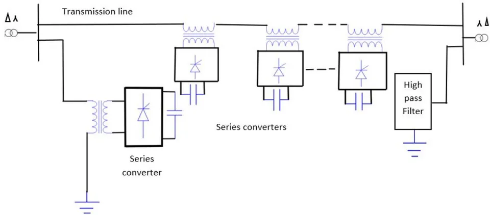
In Fig. 2, the small-sized single-phase converters rating makes the operation of the DPFC less expensive, coupled with higher reliability provided by the large numbers of series converters and improved system parameters controllability capacity compared to UPFC, which works with three-phase converters [11]. The DPFC comprises one shunt and numerous series-connected converters that can freely enhance the effective regulation capability and power flow control with lesser harmonics.
Fig. 3 shows the block diagram of the shunt control of the back-to-back configuration connection between the three-phase shunt converter and the two single-phase shunt converters. In this control system, the fundamental grid frequency absorbs the active power of the converter, and aside from this, it enhances the adjustment of the dc voltage between the capacitor and the single-phase converters and provides the shunt converter with a third harmonic current via the neutral wire of the Y transformer.
![Fig. 3: DPFC shunt control block diagram [11]](https://doc.journalspress.com/pnhb92_87887/ocr/images/derivatives/cc/cc0067d3eef41e1782b6a834ec46cf5505ba55faf0fb5d7e2ebdc35dc8b7c56c.webp)
Fig. 4 shows the block diagram of the series control where a separate series control achieves the control of each single-phase converter throughout the transmission line. In addition, during the d-q frame, the voltage of the sequence capacitor, the line current, and the series voltage reference serve as the controller input [12, 13, 14].
![Fig. 4: DPFC Series Control Block Diagram [12, 13, 14]](https://doc.journalspress.com/pnhb92_87887/ocr/images/derivatives/bd/bd857c72c0a062b4336ecc0e5d9b0956dd28ff3beea6d60122da8be19bd20321.webp)
III. COMPARISONS BETWEEN UPFC AND DPFC
The objectives of the FACT devices of UPFC and DPFC are equal, while their working principles differ. DPFC principle achieves the active power exchange between the shunt-series converters at the third harmonic frequency. Also, it enhances the respective series converters' active and reactive power compensation capability of the transmission line. In DPFC, a power line or transmission line can also transfer electrical power at the third harmonic frequency between DPFC transformers . The UPFC has two three-phase converters linked back-to-back series using a common D.C link. UPFC principle achieves power flow reliability through the line by efficiently adjusting the transmission line's voltage magnitude, angle, and impedance. The performance improvement of the UPFC and DPFC in changing voltage stability and power flow regulation through the line reduces overall harmonic distortion by minimally updating the transmission network parameters.
| Particulars | UPFC DEVICE | DPFC DEVICE |
| Control Capability | Low | High |
| Operational Reliability | Low | High |
| Noise Problem | Noisy | Less noisy |
| Electrical Efficiency | Less efficient | Very efficient |
| Converter | Two Three-phase | One single shunt and multiple independent series |
| Dc link | Present | None |
| Power Quality and Stability | Medium | High |
| Cost | Expensive due to three-phase converters ratings | Less expensive due to single-phase converters rating |
| Harmonic Problem | Reduced | Effectively reduced |
| Fault Response | High | Very high |
The primary significance of the UPFC is controlling the active power and reactive power flow through the injection of the voltage in series with the transmission line and separately varying both the magnitude and the phase angle. Thus, the UPFC is helpful in the transient improvement and moderate power system signal stability [16].
IV. SIMULATION RESULTS
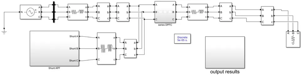
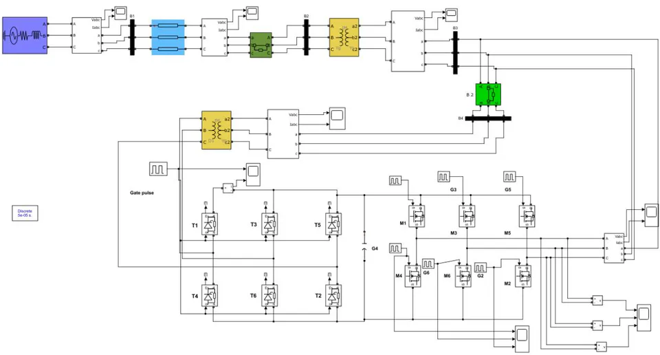
The simulation of UPFC and DPFC are performed using the MATLAB/SIMULINK software, the simulation results of UPFC and DPFC are investigated, analyzed, and compared in the work. Table 2 shows the parameters of the simulation.
| Parameter | Value |
| L-L | 380 V |
| L-L | 380 V |
| Line Impedance (L) | 5 mH |
| Load power | 20 kW |
| Frequency | 50 Hz |
| Cse | 1.8 mF |
| Csh | 1.8 mF |
| Vdc | 658 V |
{"image_source":{"path":"images/15cf9720085455d46d9d8f4289a6cde0c8e252c789018e8795965eb14bf30ce9.jpg"},"content":"","chart_caption":[{"type":"text","content":"Fig. 6 shows the voltage sag and swell on grid voltage without a DPFC device. In addition, the effects of the phase shift on the load voltage are because of the voltage sag and voltage swell that negatively affect the various load-connected equipment, thus limiting the reliability and quality of electrical power transmission."},{"type":"text","content":"Fig. 6: Grid voltage waveform without DPFC device"}],"chart_footnote":[]}
Fig. 7 shows that voltage sag and swell effects are mitigated by incorporating the DPFC device that eliminates phase shift impact to enhance the power transfer capability of the transmission systems controllability and improve system power flow.
{"image_source":{"path":"images/a71b9549e5c77c1b1b979de75a54baa37d95f7179fd9bdefdc8587f9104c002a.jpg"},"content":"","chart_caption":[{"type":"text","content":"Fig. 7: Grid voltage waveform with DPFC device"}],"chart_footnote":[]} {"image_source":{"path":"images/3090993fd465cb6cdec7c76e4b97e674d2cc4f8a149dec320e28f7fbb965ef76.jpg"},"content":"","chart_caption":[{"type":"text","content":"The series converters improve the system voltage profile, while the shunt converters control reactive power flow to maintain a constant D.C. capacitor voltage throughout the operation."},{"type":"text","content":"Fig. 8: Real source power response per unit of DPFC device"}],"chart_footnote":[]}
{"image_source":{"path":"images/f06c2c23fc0bfacbd1465f10447d9fcc9e1abfb3190002220eb535ba615cc0d5.jpg"},"content":"","chart_caption":[{"type":"text","content":"Fig. 8 shows the waveform of the real power response per unit of DPFC where the shunt's and series converters' injected power compensate for the increasing system voltage sag and voltage swell."},{"type":"text","content":"Fig. 9: Real load Power Response per unit of DPFC Device"}],"chart_footnote":[{"type":"text","content":"Comparisons Between Distributed Power Flow Controller (DPFC) and Unified Power Flow Controller (UPFC)"}]}
Fig. 9 shows the waveform of the real load power response per unit of DPFC, where the constant real power output waveform is due to the shunt and series converters' voltage compensation.
{"image_source":{"path":"images/7929ce6effd2d72f3dff5438622734b32be07514997a97416dd8b090e8241793.jpg"},"content":"","chart_caption":[{"type":"text","content":"Fig. 10: DPFC device load current third harmonic distortion"}],"chart_footnote":[]} In Fig. 10, it can be deduced that the third harmonic distortion drastically reduced to a lower value of up to 1.01%, which is considered acceptable since it's less than 5%, and this shows that the general power quality-related problems of voltage sag, voltage swell, and THD are mitigated.
{"image_source":{"path":"images/bb8fc6796f19656e6939b659351665cf314392cee5f5d6cc95e36dd76b2d773a.jpg"},"content":"","chart_caption":[{"type":"text","content":"Fig. 12: Grid voltage waveform without UPFC device"}],"chart_footnote":[]} {"image_source":{"path":"images/f21910def34c7f32e2abca997d1a76f38a325e2d95257972ee1beda894deb03b.jpg"},"content":"","chart_caption":[{"type":"text","content":"In Fig. 12, the waveform of the voltage sag and voltage swell is because of the effects of the phase shift at the load voltage."},{"type":"text","content":"Fig. 13: Grid voltage waveform with UPFC device"}],"chart_footnote":[]}
{"image_source":{"path":"images/b28b09e679bb74ce52be63e5cc610465186a750baf56070447bbc7f4a310eef4.jpg"},"content":"","chart_caption":[{"type":"text","content":"In Fig. 13, the load voltage waveform shows no voltage sag and voltage swell due to the elimination of phase shift by installing a UPFC device that controls voltage magnitude and phase angle."},{"type":"text","content":"Fig. 14: Real Source Power Response Per unit of UPFC Device"}],"chart_footnote":[]}
Fig. 14 shows the real source power response in which the UPFC device provides control of real power flow to improve the power transfer capability of the system.
{"image_source":{"path":"images/faf177537e3704c73c1e9322a87fa8a851f7e99c3f99e59d9ca1150cc9372c3b.jpg"},"content":"","chart_caption":[{"type":"text","content":"Fig. 15: Real Load Power Response per unit of UPFC Device"}],"chart_footnote":[]}
Fig. 15 illustrates the real load power response due to the addition of the UPFC device that provides power flow modulation in the system.
The simulation results show that the DPFC device performs better than the UPFC in control of the power flow profile.
V. CONCLUSIONS
The FACTS devices of UPFC and DPFC are the most versatile power factor compensators due to their excellent performance in mitigating power quality problems of voltage sag, voltage swell, voltage fluctuations, voltage imbalance, harmonics, and so on. The Matlab/Simulink simulation results show that the UPFC enhances the control of the real and reactive power flow with an injection of voltage in series with the transmission line due to the autonomous variation in both the magnitude and the voltage phase angle. Also, the UPFC can be used in the power system for transient stability of the small signal improvement. The Matlab/Simulink simulation results show that DPFC can perform better than UPFC because it provides additional flexibility by eliminating the dc-link between the shunt and the series converters. In addition, it has a low rating due to splitting the three-phase series converters into smaller single-phase converters distributed between the transmission line, which eliminates the requirement for high-voltage isolation, lower cost, and makes it simple to construct. The simulation results also demonstrate that the DPFC device can effectively reduce voltage sag and swell compared with the UPFC device. Moreover, the DPFC device can significantly reduce the third harmonic distortion in the power system.
Conflict of Interest
The authors declare no conflict of interest.
Ethical Approval
Not applicable
Data Availability
The datasets used in this study are openly available at [repository link] and the source code is available on GitHub at [GitHub link].
Funding
This work did not receive any external funding.
References
Cite this article
Related Research

Special Issue
Launch a focused special issue to highlight research, emerging trends, and expert insights in your academic field.