




IntelliPaper
Abstract
The emergence of a time-constant interaction force between a pair of antennas of sound and electromagnetic waves is shown analytically. This force is identically analytically expressed through the phases of excitation of the antennas and the distance between them both for acoustic and electromagnetic cases. Frequencies, excitation phases, and distances between the antennas were found at which the antennas maximize either the mutual repulsive (attractive) forces in a pair of antennas, or the wave thrust forces that tend to move a pair of antennas in one direction. It is shown that the force of the wave thrust of a pair of antennas is opposite to the radiation flux, which plays a role similar to gases flowing from a rocket nozzle. For a catamaran (two floats-antennas of surface gravity waves on water with a phase shift of their vertical oscillations by ) the forward motion speed and the force of wave thrust, as well as the surface jet current near the float, similar to the flow created by a propeller, were measured. In this case, the inversion of the difference in the excitation phases of the half floats simultaneously led to an inversion of the thrust force, translational motion and jet flow. The dependence of the wave thrust on the excitation frequency (with a structurally fixed phase difference ) in the experiment turned out to be similar to the analytically obtained dependences for sound and electromagnetic waves.
Explore Digital Article Text
V.
V. Arabadzhi
I. INTRODUCTION
In many boundary value problems of radiation monochromatic (at some frequency ) waves of various physical natures the force constant in time (at the frequency ) called also "wave thrust" or "steady force" arises. This force is interpreted [1-3] as the transfer of mechanical momentum by a traveling wave and equal (as a rule) to the wave energy flux divided by the phase wave speed. Steady forces of mechanical interaction of 3D emitters (antennas) via their own time-varying wave fields were first studied experimentally by Peter Lebedev [4] and Vilhelm Bjerknes [5]. In most cases, the pressure not of the radiation field itself (Fig. 1-a) on the radiating boundary was considered, and the pressure of the scattering field (reflection, Fig. 1-b) of the incident wave on the scattering body. Several decades later, the problems of mechanical interaction of small antennas began to be studied in relation to the dynamics of three-dimensional gas bubbles in a liquid and the problem of their coagulation [6-10], when the forces of attraction and repulsion between the bubbles are very important (as well as in many other complicated acoustical problems [11-14] recently).
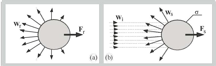 Figure 1: To the problems about pressure of the radiation field (a) and the pressure of the scattered field (b) on a body with a surface : - power flow of the incident wave, - power flow of the scattered wave, - power flow of the emitted wave, - pressure force of the scattered field, - pressure force of the radiated field.
In the 1 D boundary problem the volumetric steady force with which a plane sound wave acts on the propagation medium, taking into account the second order of its dynamics (for example, the dependence of the speed of sound on the amplitude), was considered analytically in [15]. The steady pressure of an incident sound wave on a flat reflecting interface (1D boundary problem) between two homogeneous compressible inviscid half-spaces was also considered [16], as well as the steady radiation pressure of a flat Huigence source in electrodynamics [17].
The purpose of the work [18] is to identify the similarities and differences in the manifestations of a wave thrust steady force [10] acting on a pair of small antennas irradiating each other with a fixed distance between them in application to acoustic waves, electromagnetic waves, waves on the surface of water in 3D and 1D boundary value problems. In the concrete boundary value problems for a monochromatic wave field (at the frequency ) considered below, this force is formed as the product of two components (just like the power flow) of the wave field at frequencies, which generates forces at the boundaries of a pair of antennas: power spectral density of these forces is concentrated at frequencies and .
II. WAVE THRUST OF ACOUSTICAL SMALL ANTENNAS
Let us imagine that a compressible inviscid medium (with density and speed of sound) surrounding a solid sphere (the center of the sphere is fixed at point x=0 and its radius is constant in time) oscillates uniformly in space along the axis "x" with a certain complex velocity amplitude at frequency . The medium tends to move the sphere from the point x=0 of its fixation by some force . The same force, but with the opposite sign, will act on the medium, generating waves in it. For small size ( wave number) of the sphere , the problem described above is equivalent to determining the resistance force of the medium during dipole (with a constant radius of the sphere ) oscillations of the sphere along the axis "x" near a point x=0 with complex amplitude when the medium itself is motionless (as whole). In this case, the impedance of such oscillations of a small sphere is estimated as [19]
Oscillations (and pulsations below) of the sphere are assumed to be small when the maximum displacement of the center of the sphere (or change in its radius) is much less than the unperturbed radius of the sphere, i.e.
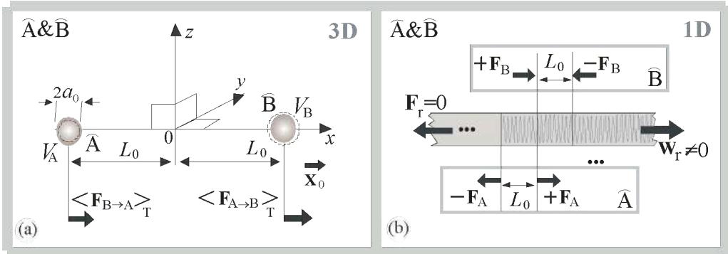
Now let us instead one sphere consider pair of identical spheres (antennas) , of radius with given pulsations velocities , at frequency , with centers fixed at points , on the axis " (see Fig. 2-a). Each of these pulsating spheres creates velocity fields , on the neighboring sphere [19]
where , ( , —given phases of spheres pulsations, —given module of velocity magnitudes, , —radius of sphere in the absence of excitation. Velocity fields and generate forces
tending to cause dipole oscillations of spheres , (with fixed centers at points ) along the axis "x", and generating scattering of the field of the sphere on the sphere (and vice versa). Here, are oscillatory dipole impedances (as stated in (1) above) of spheres. The smallness of the double (or higher) scattering of the fields of the spheres on each other guarantees, for example, inequality under the conditions and (2) (with substitution , or ). Now note that in (5) we have of impedances , of spheres , consisting of parts constant in time and variable in time and their radiuses , with given pulsation velocities , correspondingly or
where (d/dt)Z_{\mathrm{A}0}=(d/dt)Z_{\mathrm{B}0}=0, \left|\widetilde{Z}{\mathrm{A}}(t)\right|\<<\left|Z{\mathrm{A}0}\right|, \left|\widetilde{Z}{\mathrm{B}}(t)\right|\<<\left|Z{\mathrm{B}0}\right| and mean \<\widetilde{Z}{\mathrm{B}0}>{T}=\<\widetilde{Z}{\mathrm{B}}(t)>{T}=0 on time period T=2\pi/\omega_{0} is zero. The quantities \widetilde{Z}{\mathrm{A}}(t), \widetilde{Z}{\mathrm{B}}(t), V_{\mathrm{A}}(t), V_{\mathrm{B}}(t), V_{\mathrm{B}\to\mathrm{A}}(t), V_{\mathrm{A}\to\mathrm{B}}(t) are oscillating at frequency \omega=\omega_{0}. Therefore, their products \mathbf{F}{\mathrm{B}\rightarrow\mathrm{A}}=\mathbf{x}{0}Z_{\mathrm{A}}(t)V_{\mathrm{B}\rightarrow\mathrm{A}}(t), \mathbf{F}{\mathrm{A}\rightarrow\mathrm{B}}=\mathbf{x}{0}Z_{\mathrm{B}}(t)V_{\mathrm{A}\rightarrow\mathrm{B}}(t) (in (5)) have power spectral density concentrated at frequencies \omega=\omega_{0}, \omega=2\omega_{0} and \omega=0. We are interested in the latter frequency \omega=0. Substituting (6), (7) into (5) and averaging over the period T=2\pi/\omega_{0}, we obtain constant forces of interaction of pulsating spheres in time (at frequency \omega=0) \hat{A} and \hat{B}:
 Figure 2: To the problem of the wave thrust of a pair
of three-dimensional acoustic antennas: (a) a pair of pulsating spheres; (b) a one-dimensional Huygens source driven by two pairs of forces (antenna ), and (antenna ) compression-tension applied to the boundaries , , are giving zero radiation pressure force at any , , , .
are the functions (see Fig. 3-b,c), for which , , , . At we obtain the wave thrust force at or at Fig. 3-b):
and when we get strength
repulsion at and attraction at (Fig. 3-c).
Now let's calculate the relative difference between the integral radiation power fluxes forward (in the sector of polar angles) and backward (in the sector ), taking into account the projections of the radiation flux (in the far zone at a distance from the antenna ), where - radiation power directional pattern of antenna
In Fig. 3-a shows: the dependence on the wave size of the difference in power fluxes to the left and right (at ) and the directional pattern (in power, with an odd number of lobes) of the radiation of the pair at values characterized by the maximum radiation. It can be seen that the function almost mirror copies (with the opposite sign) the dependence (Fig. 3-b) of wave thrust ((10) at phases ) on the wave dimensions of the radiating system. In this case, the maximum power is always radiated in the direction opposite to the traction force . In Fig. 3-c shows: the dependence on the wave size of the forces of attraction and repulsion ((11) at phases when the traction force is zero and ) on the wave size , as well as symmetrical radiation directivity patterns (in power, with an even number of lobes) of the pair at values of , corresponding to the maxima of attraction or repulsion of antennas and .
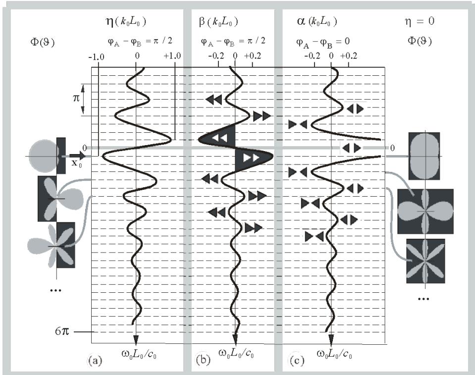 Figure 3: On the relationship between the directional pattern of the radiation power of a pair and the force of wave thrust (a) the normalized difference \eta (k_0L_0) between forward and backward radiation energy fluxes (| \mathbf{x}_0) as a function of the wave half-distance k_0L_0 between \hat{\mathrm{A}} and \hat{\mathrm{B}}, examples of radiation directivity patterns \Phi (9;k_0L0) at (\varphi{\mathrm{A}} - \varphi_{\mathrm{B}}) = \pi /2 with noneven number of lobes (petals);
(b) the force of the wave thrust of the pair ( or at and );
(c) the force of attraction ( ) or repulsion ( ) at and ), examples of radiation directivity patterns at with even number of lobes (petals).
 1D (a)
 1D (b) (c)
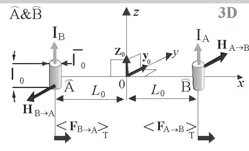
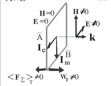
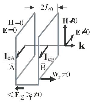
Fig. 4: To the problem of the wave thrust of a pair of electromagnetic antennas: (a) the geometry of a pair of 3D elements of electric current (antenna ) and (antenna ); (b) one-dimensional Huygens source: a pair driven by mutually perpendicular electric (antenna ) and magnetic (antenna ) currents; (c) one-dimensional Huygens source: with electric currents , located on two parallel planes, - vector of power flux density of radiation.
III. WAVE THRUST OF ELECTROMAGNETIC SMALL ANTENNAS
Let's consider two current elements \mathbf{I}_{\mathrm{A}} = \mathbf{z}0 I{\mathrm{A}}, \mathbf{I}_{\mathrm{B}} = \mathbf{z}0 I{\mathrm{B}}, where \operatorname{Re} I_{0} = I_{0} (two emitters \hat{\mathrm{A}}, \hat{\mathrm{B}} of length \mathbb{X}_0 \<< L_0, with thickness \overline{\mathbb{X}}_0 \<< \mathbb{X}_0 see Fig. 4-a), located at points x = \mathbb{X} L0. Currents I{\mathrm{A}}, I_{\mathrm{B}} create magnetic fields on each other (| \mathbf{y}_0)
which, in turn, generate the corresponding Ampere forces
Note that currents , and generate end electric charges of equal magnitude and opposite sign, oscillating at a frequency . Therefore, the Coulomb force with which the antenna ( ) acts with its electric field on the end charge of the antenna ( ) can be neglected. Thus, quantities , , , , oscillating at frequency , generate forces , , whose spectral power densities are concentrated at frequencies and ("frequency" of the wave propulsion force). From (15) we obtain expressions for the forces averaged over the period like expressions (11), (12), which differ from the acoustic case only by the factor
instead of which we need to insert
where is the magnetic constant of the vacuum. The cross-section of the radiation power directional patterns for the electromagnetic problem along a plane "x, y" coincides with the radiation patterns of pulsating spheres shown in Fig. 3. Note that in the electromagnetic boundary value problem described above, there is no both single and multiple scattering of waves by antennas , . Because currents , (precisely currents, and not implied metal vibrators) are transparent to the waves incident on them. But in the acoustic problem there is no radiation pressure on an object if this object does not scatter the waves incident on it. And yet, the dependence of forces , on quantities and remains the same as in the acoustic problem described above.
IV. WAVE THRUST OF GRAVITATIONAL WAVES ON WATER SURFACE (EXPERIMENT)
To study the horizontal wave thrust (of gravitational waves on the surface of the water surface), a catamaran was made, consisting of two identical rectangular floats (antennas) and with dimensions (see Fig. 5-a). The floats , are made of light and rigid (relative to the water surface) foam plastic, oriented parallel to each other with respect to their length and rigidly connected to each other by a plate of the same foam plastic. This catamaran was placed in basin of water volume of dimensions (the last is depth). Vertical oscillations of the floats , are provided by two identical synchronous in-phase electric drives , the axes of which rotate in mutually opposite directions at frequency (Hz). Rigid thin light rods of length are rigidly attached to the ends of the axles of each electric drive, rotated relative to each other on the axis by an angle ; point masses are fixed to these light thin rods. The action on the catamaran of inertial forces of rotating masses attached to the axes of different drives is mutually compensated in the horizontal direction. Thus, the rotation of the masses by electric drives provides vertical forces applied to the floats and shifted relative to each other in phase by . The physical mechanism for creating wave thrust is the same as in the acoustic problem in Section 1. The sinusoidal (with frequency ) immersion of the float (or ) simultaneously performs two functions: (a) radiates a wave traveling towards the float (or ); (b) modulates in time with frequency the horizontal component of the force (proportional to the depth of immersion) with which the float (or ) is acted upon by a scattered wave generated by a wave coming from the float (or ). Thus, similar to Section 1, by selecting the necessary phases of oscillations of the floats, the distance between them and the excitation frequency, we hope to obtain a non-zero time-average horizontal force of the catamaran wave thrust or in other words to obtain scattered field at frequencies and f=0 (reactive flow).
When constructing the model , the main goal was to ensure geometric symmetry, hydrostatic symmetry and symmetry of moments of inertia, so that the asymmetry of the phases of rotation of the masses would manifest itself most clearly and a small wave thrust would become noticeable. At low frequencies, the wave thrust is "overshadowed" by unaccounted waves reflected from the walls of the basin (four meters wide) at the small inertia forces of the loads driving the model, as well as multiple scattering between the floats and . At high frequencies, the wave thrust is "overshadowed" by the viscosity of the liquid. However, despite the interfering factors described above, the maximum force N (force measurements were averaged over at least four wave periods) of wave thrust was found at a frequency Hz when the model was fixed horizontally (i.e., at and the maximum speed m/s of dust particles in the jet flow on the surface of the water (see [20]), and the maximum speed of the model, freed from horizontal fixation, reached value m/s. The dependence of the wave thrust force on frequency in the range from 2.0 Hz to -2.0 Hz was experimentally recorded, qualitatively similar to Fig. 3-b (black section of the function ) marked by black thick vertical lines which present the bounds of measurement errors. Quite remarkable is the fact that when the sign changing of the rotation frequency (or when changing ) of the masses changed, the wave thrust force also changed the sign, saving its absolute value. In addition, at the picture of the flow on the water surface was completely inverted ( ). In this case, the load with the previously "lagging" phase of rotation became "advanced" (and vice versa). Two axes of rotation of the loads are needed so that the driving force of inertia of the loads does not have even an instantaneous projection onto the axis "x" (the direction of the expected wave thrust). In Fig. 5-a shows the design of a catamaran. Fig. 5-b shows a top view of the catamaran as well as the calculated cardioid radiation pattern (highlighted white field) and the structure of the vortex jet flow on the water surface similar to the flow around the propeller. Fig. 5-c represents the optimal frequency of rotation of the drives , the wave semi-distance between the floats and , and the phase and rotation of the masses , at which the force of the wave thrust and the speed of the jet stream of the attached catamaran, as well as the translational wave thrust and the speed of the jet stream of the attached catamaran, as well as the translational speed of the freed catamaran are maximum. Fig. 5-d presents the experimental dependence of the wave thrust force on the rotation speed of electric drives , similar to (11) and Fig. 3-b.
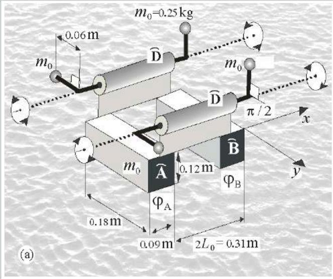
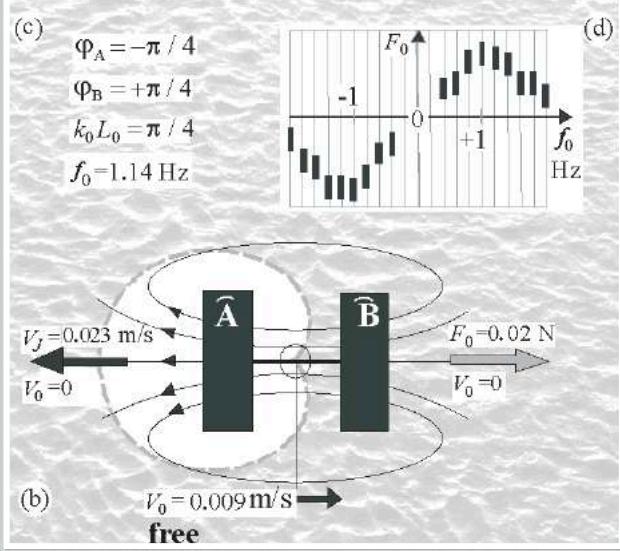 Figure 5: About the experiment with surface gravity waves on water: (a) the design of the model
(wave mover) from floats and identical masses located on axes with opposite sign and equal in magnitude rotation frequencies determined by electric drives , the phases , of rotation are determined by the angle of attachment on the axis of rotation; b) top view (cardioid directional pattern of radiation and streamlines of the jet stream) as well as the highest values of the force of wave thrust and the speed of particles of the jet stream with horizontal fixation ( ) of the model , horizontal speed of the model in free motion; (c) optimal parameters for creating wave thrust of the model used (a); (d) dependence of the wave thrust force on the excitation frequency of the model (see also Fig. 3-b)
V. WAVE MOVER AND HUIGENCE SOURCE
Since wave propulsion requires a difference in radiation power "forward" and "backward," below we will consider the similarities and differences in the design and characteristics of a 3D, 1D wave mover (WM) and a 3D, 1D Huygens source (HS) based on a two-element antenna.
The construction of WM and HS at 3D dimension: WM are two small spheres pulsating with speeds , in Fig. 2-a (or current elements , , Fig. 4-a) with phases , (regardless of frequency ); HS - the same two spheres (or current elements ) with phases of speeds (currents) and (proportional to frequency ).
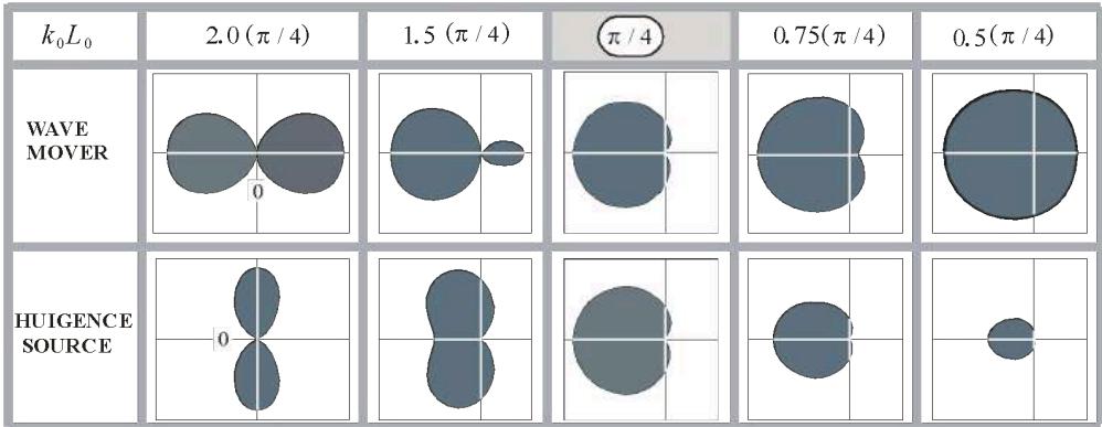 Figure 6: Directional patterns (in terms of power) of an acoustic wave propulsion device (3D mover, see
Section 2) and a Huygens source for different wave sizes of the device and identical amplitude modulus of the normal oscillatory velocity on the surface of pulsing spheres (the intersection of the vertical and horizontal axes means zero power)
The requirement for a wave propulsion device is the maximum force of wave propulsion. The requirement for a Huygens source is a zero radiation pattern in one direction "forward" and non-zero radiation in the direction "backward" while saving (at ) a constant shape of a single-lobe cardioid radiation pattern. The requirements for WM and HS and their characteristics are different (see Fig. 6), however, the combination of parameters , , is a special case (Fig. 5-c) when WM and HS are identical to one another and the traction force (11) is maximum (see Fig. 3-b). In the 3D case it is possible to create WM both for waves in a compressible inviscid medium and for electromagnetic waves in a vacuum.
In the 1D performance HS and WM are equivalent to one another at all frequencies . It is possible to create HS (see Fig. 4-b,c) for linear (in vacuum) electromagnetic waves (with the traditional expression for the wave thrust force density, where is the flux density vector of unilaterally radiated power. For example flat electromagnetic HS on one plane : flat electric current produce the electric field which acts on perpendicular flat magnetic current and on the other hand flat magnetic current produce the magnetic field which acts on perpendicular flat electric current by Ampere force.
On the other hand, one can guess that the force of wave thrust (in the case of waves caused by vibrations of the masses of matter) is created by the vortex jet flow described in Section 3 and Fig-5-b (or acoustic flow for sound waves). After all, we assumed the wave fields to be stationary. The absence of avoiding (diffraction) of 1D obstacles (antennas) by such waves would mean the absence of a reactive vortex flow, because a spatially one-dimensional vortex is impossible. For example, an 1D unsupported HS is driven by pairs , of mutually opposite and equal in modulus forces ([20], [21] see Fig. 3-b) in the infinite homogeneous media, therefore such a source does not create reactive recoil at any frequency, including the zero frequency of the wave thrust force that interests us.
VI. CONCLUSIONS
The interaction of the simplest local emitters (small antennas) is analyzed analytically: two pulsating spheres in acoustics and two current elements in electrodynamics. An identical dependence (up to coefficients (16), (17)) for both cases (11), (12) of the interaction force on the distance between the emitters, their sizes, as well as the frequency, amplitude and phases of their excitation was obtained.
Formulas (11), (12) describe the effects of attraction, repulsion and propulsive action of emitters on each other.
Despite the identity of the above-mentioned analytical dependence (11), (12) in the acoustic (Section 1) and electrodynamic (Section 2) cases, there is a fundamental difference. Acoustic forces (11), (12) of interactions are generated by the modulation (Section 1) in time of the radii of the spheres , ) and, accordingly, the modulation of the fields scattered by them, i.e. scattering plays a fundamentally important role in the generation of steady acoustic thrust force (10) of small antennas. But in the case of electromagnetic waves, to generate steady components of forces (15), scattering (and modulation of scattering in time) is not required at all, because the current element (emitter or ) does not create a scattering field (single or multiple scattering).
In addition, in the case of gravitational waves (Section 3), a vortex jet flow (Fig. 5-b) and wave thrust of a catamaran float were experimentally detected on the water surface, the dependence of which on the frequency (Fig. 5-d) and on wave dimensions of the device is similar to the function (11) (Fig. 3-b), obtained for acoustic and electromagnetic waves (Sections 1, 2).
The results above obtained in the article can find potential application in the development of wave propulsion devices for the transfer of physical bodies and allow us to better understand the energy efficiency of such devices for acoustic waves, electromagnetic waves and gravitational waves on water surface.
ACKNOWLEDGMENTS
This work was supported by Project FFUF-2024-0035 of the Institute of Applied Physics (RAS).
Conflict of Interest
The authors declare no conflict of interest.
Ethical Approval
Not applicable
Data Availability
The datasets used in this study are openly available at [repository link] and the source code is available on GitHub at [GitHub link].
Funding
This work did not receive any external funding.
References
Cite this article
Related Research


Special Issue
Launch a focused special issue to highlight research, emerging trends, and expert insights in your academic field.
