



IntelliPaper
Abstract
The features of the electric explosion of spiral-shaped conductors in the RLC discharge circuit are considered. It has been experimentally established that during the explosion of spiral-shaped wires in water, in contrast to the explosion in air, the secondary breakdown occurs along the spiral ionized channel due to the greater density of the environment, the lower expansion rate of the explosion products, and the compressive effect of the discharge channel of its own magnetic field. The nature of the discharge process is determined by the increase in the active resistance of the spiral plasma channel during its expansion. Due to the additional action of magnetic pressure generated during the explosion of the spirals, the force effect on electrically conductive objects located inside or outside the spiral increases, which can be used when distributing pipes in tube grids and loading samples with high pulse pressure. In addition, when changing the initial parameters of the spirals (number of turns, pitch, diameter) during their explosion in water, in the discharge circuit it is possible to observe the nature of the discharge from deeply oscillatory to deeply aperiodic, including obtaining a single pulse of discharge current for its use as a breaker for high-power electrical circuits.
Explore Digital Article Text
I. INTRODUCTION
The phenomenon of electrical explosion of conductors, which has been widely studied since the middle of the last century, has found practical application in various branches of industry . One of the most developed and implemented in production can be called the deformation and pressing of pipes in pipe lattices, in particular in heat exchangers of nuclear power plants , in which the electric explosion of spiral wires was used. In works assumptions were made about the need to take into account the electromagnetic forces that arise when the discharge current flows through the spiral channel formed as a result of the electric explosion of wires of the corresponding shape during the explosion of spirals.
For the first time, possible changes in the distribution of the intrinsic magnetic field during the explosion of spiral-shaped wires in a vacuum were presented in the work , where it was shown that the current flows along the spiral in the first.
Stage of the discharge, when energy is introduced into the wire for the explosion, and the magnetic field strength inside it is determined by the number of ampere turns. This stage in the experiment lasted for about 10 mcs, after which a breakdown occurred between the turns with their overlap by the discharge current. The speed of movement of the explosion products in a vacuum calculated in the work was m/s, and the maximum magnetic field strength was A/m.
The present work sets the task of studying the electrodynamic processes accompanying the spiral electric explosion, as well as their influence on the magnitude of the force interaction with the objects of processing. For this purpose, experimental studies were conducted on the features of the electric explosion of spiral wires compared to the linear one in media of different density. The influence of the self-magnetic field of exploding spirals on the electrical characteristics of the discharge process was considered. High-speed photography, measurement of electrical characteristics (current, voltage) in the RLC discharge circuit, and measurement of the magnetic field intensity inside exploding spirals using a special probe in air and water were carried out. During the experiments, the following parameters for the reference points were changed: electrical capacitance , discharge circuit inductance , capacitor charging voltage , length of exploding aluminum wire , 300, 750 mm, wire diameter in all cases was . The diameter of the spirals made of wires of the specified length varied in different series of experiments within the range . The number of turns N and the pitch of the spirals p were selected in accordance with the expressions: ; , where lwir is the length of the wire, mm; is the length of the spiral, mm. The length of the spirals was and 40 mm. Thus, these parameters varied within the limits of tur, p = 1 - 12 mm. The spiral with a diameter of 42 mm was a helically bent wire with a length of 145 mm, placed between the electrodes at a distance between them of , which corresponded to one turn, and the magnetic field inside it was minimal with the chosen initial parameters of the experiments.
The influence of the density of the surrounding environment on the nature of the explosion processes and the flow of the discharge current can be seen in Fig. 1, which shows the results of shooting spiral explosions in air and water using a high-speed photo recorder.
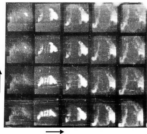
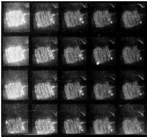
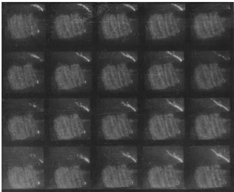
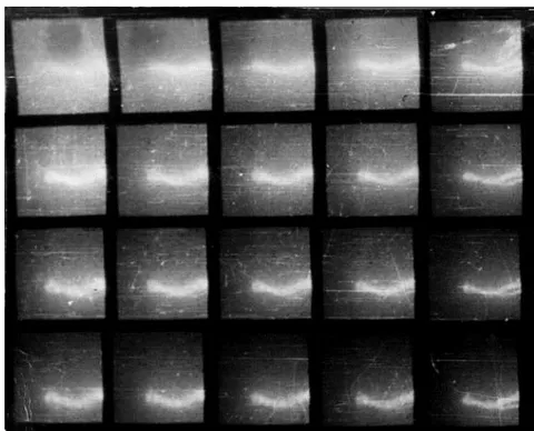
c) Overlap between spiral turns, linear discharge configuration kV, m/s, mcs.
Fig. 2 shows the corresponding Fig. 1 a),b1),b2) measured in experiments changes in currents and magnetic field strengths in the center of the spirals.
From Fig. 1, 2, the following conclusions can be drawn. Before the beginning of the second stage of the discharge, during the melting and evaporation of the wires, their spiral shape is preserved in both environments. In this case, a characteristic current drop is observed, caused by the pressure of the explosion products (Fig. 2a, b). Further, differences are observed both in the expansion rates of the explosion products (Fig. 1) and in the nature of the currents flowing during this, as well as the pulses of magnetic field strengths (Fig. 2c, d).
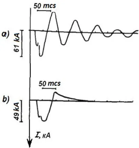
{"image_source":{"path":"images/453eda5617ae64e283b4b8c919ca6ac4163851d3744cce1bb0bb555c14998819.jpg"},"content":"","chart_caption":[{"type":"text","content":"Fig. 2: Oscillograms of the discharge current I (a, b) and the corresponding magnetic field strength H (c, d) during the explosion of spirals in air and water."}],"chart_footnote":[]} For the explosion of the spiral in water, the nature of the current, all other things being equal, changed to a pulse with a surge of reverse polarity, aperiodically decaying (Fig.2b). In this case, the magnetic field intensity pulse corresponds in shape to the discharge current pulse. Its amplitude value, measured in the center of the spiral, is A/m. m/s. The current during an explosion in air (Fig. 2a) has an oscillatory nature with a half-period T/2 = 50 mcs, and the magnetic field strength pulse has the following parameters: amplitude A/m, duration 7 - 8 mcs, pulse front 1 - 2 mcs. In air, the radial expansion velocity of the spiral explosion products is m/s, and the spiral shape of the wire is destroyed within 3 - 4 mcs from the beginning of the process (Fig. 1a). Table 1 shows the values of the expansion rates of the explosion products of spiral conductors in water and air, where it is shown that the expansion rates of the spiral discharge channel are different both in the radial direction of the spirals and in the axial (along the axis) .
| No in order | Initial data of the experiments | Explosion product expansion velocity(radial Vr, axial Vz), m/s |
| 1 | Spiral, explosion in water, , , N = 6 wir. | |
| 2 | Spiral , , , N = 9 wir. | |
| 3 | Linear discharge configuration | |
| 4 | Wire , | |
| 5 | , Spiral, , | |
| 6 | Spiral, explosion in the air, , , N = 6 wir |
For comparison, Table 1 shows the expansion rate of the linear discharge channel, caused only by the pressure of the explosion products , which is almost 2 times less than the increase rate of the spiral diameter, caused by the combined effect of both magnetic and gas-kinetic pressures on the expansion of the spiral plasma channel. The velocity values indicate an additional influence of the magnetic field concentrated inside the spiral on the radial velocity of its expansion. For identical experimental conditions, judging by the radial expansion velocities (180 m/s for the spiral and 110 m/s for the linear channel), the values of magnetic and gas-kinetic pressures on the turns of the spiral discharge channel are comparable in order of magnitude, therefore the additional effect of magnetic pressure on the turns from inside the spiral leads to an increase in the radial expansion velocity by almost 2 times. Comparison of the radial velocities of the coil expansion in the axial direction of the spiral, along its axis (respectively, 30 m/s and 110 m/s), indicates the deceleration of the discharge channel expansion in this direction. In addition, the conclusion suggests itself that from the beginning of the discharge process to the second stage of the discharge in both media (air, water) the spirals retain their shape. In air, at the end of the first stage, the spiral shape is destroyed due to the high speed of the explosion products, and the second stage becomes linear. In this case, the current oscillogram has an oscillatory nature (Fig. 2a). The duration of the magnetic field intensity pulse inside the spiral in air corresponds to the explosion time before the onset of the second stage of the discharge. And the nature of the discharge current is determined by the RLC parameters of the discharge circuit, in this case it is a deeply oscillatory process. It is precisely this nature of the processes that the authors observed during the explosion of spirals in a vacuum in .
Unlike an explosion in air, in water the current flows through a spiral channel during the entire discharge process, including the second stage. As in any solenoid, two components of the force of electrodynamic interaction begin to act on it. Axial , which tends to compress the solenoid from the ends to the center, and radial , which tends to break the turns in the radial direction. As a result of the action of , the radial expansion rate of the spiral channel increases compared to the linear one. The decrease in the channel expansion rate in the axial direction of the spiral indicates the deceleration of the discharge channel due to magnetic forces during the interaction of the current in the turns of the spiral. This is evidenced by a slight decrease in the total length of the spiral channel within 30 mcs from the beginning of the discharge process (see Table 1). Further expansion of the spiral in this direction occurs with the expansion of the outer turns of the spiral on both sides due to gas-kinetic pressure.
{"image_source":{"path":"images/6b6023cf26741e990e481eee38b2fa9ec5a1b10a412cc8a7a47bf8e8f53852f0.jpg"},"content":"","chart_caption":[],"chart_footnote":[]}
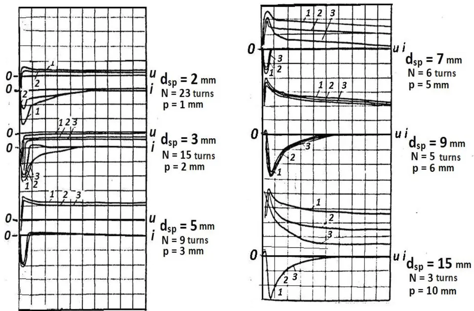
{"image_source":{"path":"images/f2f92bc634391a22f88550a2ce6caa21c5be2575cdd57660ebda6a4a55009bf8.jpg"},"content":"","chart_caption":[{"type":"text","content":"Fig. 3: shows oscillograms of current and voltage during the explosion of spirals in water."}],"chart_footnote":[]}
Fig. 3 Oscillograms of current and voltage during the explosion of spirals in water. , . Scales: current i - 3 kA /div, voltage u - 4.4 kV/div, time t - 10 mcs/div. , C = 3 mcF,
The spirals are made of wires of the same length mm. The diameter of the spirals varied within mm. Three experiments were conducted per point. It should be noted that the data scatter is satisfactory for both current and voltage. In all cases, when the spirals explode, a pattern is observed - the voltage does not drop to zero simultaneously with the current, but continues to be applied to the gap. This residual voltage is quite high and in some cases is more than half the voltage initially applied. This fact indicates that the resistance of the discharge channel during the explosion of spiral-shaped wires in water increases so much that it slows down the discharge process after the explosion. This fact indicates that the resistance of the discharge channel during the explosion of spiral wires in water increases so much that it slows down the discharge process after the explosion.
The active resistance of the discharge circuit, taking into account the resistance of the spiral plasma channel in water R (t), was calculated using expression (1), when the cross-section of the plasma channel was approximated by an ellipse, and the rates of change in the dimensions of the spiral were taken from the experiment. The change in electrical conductivity was taken into account by means of the action integral until the moment of evaporation of the conductor [7, 8]:
where: is the active resistance of the circuit, Ohm (calculated based on the degree of current attenuation on the oscillogram of a short circuit of the circuit , where is the degree of short circuit current attenuation); N is the number of turns of the spiral; dsp, rwir are the diameter of the spiral and the radius of the wire; is the experimental value of the radial expansion velocity of the spiral plasma channel; is the electrical conductivity of the material at ; is the semi-major axis of the elliptical cross-section of the expanding plasma spiral channel; is the expansion velocity of the linear channel; is the semi-minor axis of the ellipse; is the expansion velocity of the spiral in the axial direction (along the axis); is the thermal coefficient for aluminum; is the action integral until the moment of conductor evaporation. The calculations were performed for the following initial parameters of the spirals: wire material - aluminum, ; 300; 750 mm, . The initial active resistance of the 145 mm long wire was 0.018 . Calculations showed that for a spiral at N = 6 turns at the moment t = 5 mcs, , and (in the Table 2). The ratio of active Rt and reactive resistances is equal to m = 2.1, the nature of the current in the experiment is close to a single pulse. For a spiral , made of wire and N = 9 tur at for t = 5 mcs, , , and m = 10.9, which corresponds to the deeply aperiodic nature of the discharge current in the experiment.
Table 2 presents the initial data of the experiments, the results of calculating the change in the active resistance , the inductance of the spirals for the time t = 5 mcs from the beginning of the discharge process, the active Rt, reactive Rr resistances and their ratio , as well as the results of experiments on the observed current pulses during the explosion of spiral wires. As is known [9], with a ratio of active and reactive resistance in the RLC discharge circuit m = 2, a single pulse should be observed. At m < 2 the discharge is oscillatory, and if m > 2, the discharge should have an aperiodic character with a corresponding increase in the steepness of the pulse front and a decrease in its amplitude. The inductance of the discharge circuit, taking into account its change during the expansion of the spiral discharge channel after the explosion, was calculated using the method described in [10].
| No in ord. | Parameters of the discharge circuit and the exploding element (initial dimensions) | Calculation at t = 5 mcs | Experiment | |||
| Active resistance of the | Discharge channel inductance | Reactance , Ω | m= Rt/Rr | Current pulse character, front/fall,mcs | ||
| discharge channel | ||||||
| 1 | 2 | 3 | 4 | 5 | 6 | 7 |
| 1 | Linear wire mm, mm, mcH, C = 9 mcF, kV | 0,7(39) | 0,08(0,02) | 0,73 | 0.93 | Oscillatory half-period T/2 = 15 mcs, ( kA) |
| 2 | Spiral mm, mm, mm, N = 4 tur., mcH, C = 9 mcF, kV | 1.78(99) | 0.066(0,013) | 0.57 | 2,37 | Single, 3,0/5,3; (30.2) |
| 3 | Spiral mm, mm, mm, N = 6 tur. mcH, C = 3 mcF, kV | 3,8(211) | 0.078(0,24) | 3.0 | 2,1 | Single, 4,0/5,3, (7,8) |
| 4 | Spiral mm, mm, mm, N = 6 tur., mcH, C = 9 mcF, kV | 2,21(123) | 0,078(0.82) | 9,0 | 3,1 | Aperiodic, 0/60,0, (10,2) |
| 5 | Spiral mm, mm, mm, N = 9 tur., mcH, C = 9 mcF, kV | 8,47(470) | 1,05(0,26) | 0.77 | 10.9 | Aperiodic, 0/60,0, (5,0) |
| 6 | Spiral mm, mm, mm, N = 6 tur., mcH, C = 30 mcF, kV | 2,26(58) | 0,21(0,04) | 0,41 | 5,6 | Aperiodic, 0,0/20, (30,0) |
From the results of explosion of long wires 760 and 300 mm, twisted into spirals, presented in the table, it can be concluded that in the case when the explosion itself does not occur, but overheating of conductors characteristic of such wires is observed, after the discharge in water a plasma or liquid metal spiral is formed with a characteristic change in the degree of attenuation of the discharge current towards aperiodicity. In calculations after t = 5 mcs from the beginning of the discharge process, an increase in the active resistance of the circuit is observed due to the expansion of the spiral with an increase in the length of the discharge channel by 40 - 470 times. At the same time, the total inductance increased by this time by 1,1 - 1,3 times. This confirms the initial assumption that the main role in changing the nature of the discharge process during the explosion of spirals is played by the growth of the active resistance of the discharge channel, which grows due to the increase in its length. Comparison of calculations and experiments shows their satisfactory agreement. The use of spirals with a number of turns N = 4 - 9 tur for RLC circuits in experiments made it possible to obtain single current pulses with a front of 3 - 5 mcs, which suggests the possibility of using them as circuit breakers for energy sources with an amplitude current of the order of tens of kA. Another example of the use of a magnetic field of the order of A/m, observed during the electric explosion of spiral wires in water, can be devices for compression of magnetic flux [11].
The discharge current in the range of spiral diameters of 7 - 10 mm (N = 6 - 4 tur) has an aperiodic character or the character of a single pulse. With smaller diameters and, accordingly, a larger number of turns and a smaller pitch, a complete or partial overlap between them by plasma occurs, the discharge takes a linear form, the magnetic field strength decreases and, accordingly, as experiments have shown, the current has an oscillatory nature. With large spiral diameters (more than 10 mm), the number of ampere turns decreases with a corresponding decrease in the magnetic field strength inside the spiral. The current character is again oscillatory. It should be noted that the effectiveness of the impact on the object loaded during the explosion of the spirals, for example, a deformable pipe, is maximum in the region of spiral diameters mm, N = 4 - 6 tur, when the magnetic field inside the spiral is maximum, the rate of expansion of the spiral is also maximum, which is preferable in technological processes of metal pressure treatment using cylindrical geometry of deformable parts. However, it should be borne in mind that additional requirements should be imposed on the high-voltage insulation of the process unit in order to avoid discharges on the tube sheet and ineffective impact on the deformable pipe.
In accordance with the amplitude values of the discharge current and the values of the maximum magnetic field strength in the center of the spirals, measured in the experiments, the magnetic pressure Pm on the turns of the exploding spiral was calculated using expressions (2), (3) [8]:
where: is the winding density of the spiral; is the magnetic field strength in the center of the spiral.
Fig. 4 shows the results of calculations of the magnetic pressure inside the spirals on their turns based on the values of the measured discharge current (curve 1a), as well as on the measured values of the magnetic field strength (curve 1b). Dependence 2 takes into account the overlap between the turns. Dependence 3 is hypothetical under the assumption that there was no overlap between the turns.
Dependence 2 takes into account the overlap between the turns. It is evident that the value of magnetic pressure increases due to the change in the shape of the spiral and the number of turns by almost an order of magnitude and reaches values of Pa. Under the influence of this pressure, the rate of expansion of the spiral increases, the total length of the discharge channel increases and, accordingly, its active resistance. The value of magnetic pressure for the experimental conditions is comparable in order of magnitude with the hydrokinetic pressure developed during the actual electric explosion. Therefore, one can assume, for example, the following mechanism of tube distribution in tube grids during the explosion of spiral wires. At the beginning of the discharge current flow, primary deformation of the loaded pipe due to magnetic forces, and then additional impact action due to hydraulic shock compacts the pipe expansion site. Thus, the quality of pipe expansion is improved.
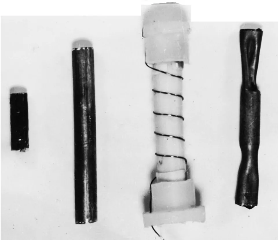
{"image_source":{"path":"images/0304562bbcf4ab1714276759c8f91a4279bac7e288418185c1223378884dd769.jpg"},"content":"","chart_caption":[{"type":"text","content":"Fig. 4: Dependence of magnetic pressure on the turns of the spiral on its diameter. 1a - calculation based on the measured current amplitude; 1b - calculation based on the measured magnetic field strength; 2 - taking into account the overlap between the turns; 3 - without taking into account the overlap between the turns."}],"chart_footnote":[]} As an example of the effect of the self-magnetic field of a spiral exploding wire in water, loading was carried out on graphite samples (far left in Fig. 5) with the following dimensions: length 40 mm, diameter 5 mm. The sample was placed in a copper tube (second from the left in this figure) with a wall thickness of 1 mm. The sample was wrapped in aluminum foil with a thickness of 40 mcm, which after loading exploded due to the currents induced in it, thereby providing additional gas-dynamic pressure acting on the sample [12].
II. CONCLUSIONS
A spiral-shaped discharge plasma channel, formed as a result of an electric explosion in water of a wire of the corresponding shape, represents a variable resistance, increasing during the discharge process in comparison with its initial resistance by several orders of magnitude due to an increase in the length of the discharge channel.
By changing the initial parameters of the spiral wire (wire length, number of turns, spiral pitch), it is possible to obtain discharge characteristics from deeply oscillatory to deeply aperiodic at the secondary stage, including obtaining a single current pulse that can be used to open high-power electrical circuits.
When a spiral wire exploded in water, a magnetic field strength of about A/m and a pulsed magnetic pressure on a sample of about Pa in a volume of cubic cm with a duration of up to 100 mcs were recorded. A magnetic field with such parameters and in such a volume can be used in metal deformation technologies, loading samples with high pressure, and also as a source of initial magnetic flux during magnetic cumulation.
ACKNOWLEDGEMENTS
The authors are grateful to PhD of EngS Telyashov L.L. for useful discussion and to Cand. Of EngS. Poklonov S.G. for assistance in conducting the experiments.
Conflict of Interest
The authors declare no conflict of interest.
Ethical Approval
Not applicable
Data Availability
The datasets used in this study are openly available at [repository link] and the source code is available on GitHub at [GitHub link].
Funding
This work did not receive any external funding.
References
Cite this article
Related Research

Special Issue
Launch a focused special issue to highlight research, emerging trends, and expert insights in your academic field.