


IntelliPaper
Abstract
A physical model is presented for hydrogen bonding in an effort to better understand the impact of electric fields on hydrogen bonds in human cells. Using fundamental dielectric physics and hydrogen-bonding in cell membranes, the model indicates that little/no membrane degradation will occur for external electric fields of ≤ 200V/cm. The model also indicates that significant damage to the cell membrane will commence at external fields as low as 1kV/cm, strong and irreversible cell membrane degradation will occur at 10kV/cm, and catastrophic cell membrane damage will occur at 40kV/cm. Any cell membrane degradation (that permits water molecules to permeate the normally hydrophobic cell membrane layer) is shown to be particularly devastating for H-bond breakage. This work is important not only for determining the safe-levels of external electric field for humans but also the external field levels that impact the electroporation process where cancer cell membranes are purposely broken down with electric field.
Explore Digital Article Text
I. INTRODUCTION
Human life, as we know it, cannot exist without hydrogen bonds (H-bonds). These bonds are essential for the functioning of biological molecules such as DNA and proteins. However, the H-bonds are relatively weak ( ) versus the much stronger ionic and covalent bonds ( ). In chemistry, H-bonds have historically been described symbolically as X - H ---- Y. Here, X - H represents a strong bond (ionic and/or covalent) between atom X and H and H --- Y represents a much weaker electrostatic bond to a neighboring polar molecule.
In biochemistry, X usually stands for Oxygen or Nitrogen. Since X and H have significant differences in electronegativity, the electron cloud around the H atom will be shifted more towards X. This electron cloud shifting results in H becoming more positively charged and X becoming more negatively charged. In chemistry, this electron cloud shifting is generally referred to as increased polar bonding while in physics this is generally referred to as a dipole formation. With the H now positively charged, the hydrogen can form a weak electrostatic bond with the negative end of an adjacent polar molecule. Thus, the bonding between the polar molecule X - H and the polar molecule Y can be described as a dipole-dipole interaction.
The modeling for the impact of electric field on H-bonds will begin with a look at the fundamental physics and chemistry of hydrogen bonding and its importance for living organisms. This is followed with a short review of fundamental dielectric physics and the development of the CCD-Model for the human cell. The impact of external field on H-bond degradation is given special attention with an emphasis on both safe-levels of electric fields for humans and electric field levels that are important for electroporation. The paper is concluded with a detailed look the frequency dependence of pulsed electric fields on cell membranes.
II. HYDROGEN BONDS (H-BONDS)
Shown In Fig. 1 are two interacting dipoles. This dipole-dipole interaction potential energy can lead to an H-bonding state (negative potential energy state).
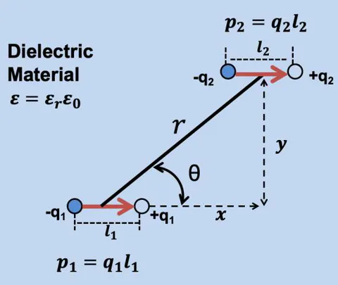
Generally, from Eq.(1), one can see that the maximum bonding potential energy (most negative potential energy U) occurs at while the repulsive potential energy (U is positive) starts at .
To further illustrate the H-bond energy dependence on bonding angle, in Fig. 2 we have used dipole moments of , a bonding distance between dipoles of , and a free space permittivity of . We see that the H-bond energy has a strong dependence on H-bonding angle and on the relative dielectric constant of the material in which the H-bond is imbedded.
{"image_source":{"path":"images/26ea44039b0f20aea063a8edbf3e4fe9ddb70ce8b945703ee66c009407df61c2.jpg"},"content":"","chart_caption":[{"type":"text","content":"Fig. 2: H-bond energy as a function bond angle "},{"type":"equation_inline","content":"\theta"},{"type":"text","content":" and relative dielectric constant "},{"type":"equation_inline","content":"\varepsilon_{r}"},{"type":"text","content":". No bonding ("},{"type":"equation_inline","content":"U \geq 0"},{"type":"text","content":") occurs for "},{"type":"equation_inline","content":"\theta \geq 54.7"},{"type":"text","content":" degrees"}],"chart_footnote":[]} For calculations that follow, it is instructive to express Eq. (1) in terms of the lateral separation distance x and the vertical separation distance y (as was illustrated in Fig. 1):
H-bond potential energy is shown in Fig. 3 (as a function of the lateral distance x for a fixed vertical distance ) for materials with different relative dielectric constants.
{"image_source":{"path":"images/5f17172cec53f25e1b3fe5656e0a453268402ea9ef679b559f06463de07ee100.jpg"},"content":"","chart_caption":[{"type":"text","content":"Fig. 3: H-bond potential energy as a function lateral distance x between dipoles with a fixed vertical separation of "},{"type":"equation_inline","content":"y=2.7\AA"},{"type":"text","content":". Strongest bonding (minimum energy) occurs for lateral distance of "},{"type":"equation_inline","content":"x = 2.4\AA"},{"type":"text","content":", giving a desired bonding angle for this particular charge configuration of "},{"type":"equation_inline","content":"\theta \cong 48.4^{\circ}"}],"chart_footnote":[]} In Fig. 4, we show both the lateral-distance dependence x and the vertical-distance dependence y for the interacting dipoles that were shown in Fig. 1. In these calculations, was used because of its importance when we discuss H-bonding in cell membranes (found later in Section V).
{"image_source":{"path":"images/d13d825b9119b185a2b07b66c09c36085cf7cf69d0545c2e3c9fbbecf83be06d.jpg"},"content":"","chart_caption":[{"type":"text","content":"Fig. 4: The impact of horizontal displacements (x) and vertical displacements (y) on H-bond potential energy in a dielectric material of relative constant "},{"type":"equation_inline","content":"\varepsilon_{r} = 3"},{"type":"text","content":"."}],"chart_footnote":[]} In the work that follows, the impact that an external electric field has on H-bonding will be investigated in terms of field-dipole interaction. Since H-bonding is fundamental for cell life, then a predictive physical model for field-induced H-bond degradation could be very useful. The physical model could be used for not only determining safe levels of external electric field for human beings but also be used for determining optimal external electric-field levels for electroporation of cancer cells
III. IMPACT OF EXTERNAL FIELD ON H-BONDS
Shown in Fig. 5 is a H-bond in the presence of an electric field in the dielectric material.
{"image_source":{"path":"images/48a810d7c3ca6b279ffb4bbc96b0c105ae0f9e86ecfc61a8d1c15cc47bd61c6d.jpg"},"content":"","chart_caption":[{"type":"text","content":"Fig. 5: The H-bond in the presence of an electric field in a material with relative dielectric constant "},{"type":"equation_inline","content":"\varepsilon_{r}"},{"type":"text","content":"."}],"chart_footnote":[]}
The impact of the electric field on the H-bond potential energy is given by:
If we assume that the dipoles are approximately of equal magnitude and opposite to the field (as illustrated in Fig. 5), then the field-dipole interaction serves to increase the potential energy of the H-bond (and thereby reduces the H-bond energy) by the amount:
Thus, we see that fields in the dielectric material approaching 1MV/cm will have an impact on reducing the H-bonding energy. As will be demonstrated in Section VI, fields in the cell membrane layers can easily approach and exceed 1MV/cm during electroporation procedures.
IV. IMPACT OF WATER MOLECULES ON H-BONDS
Water is an exceptionally effective solvent for polar-bonded materials. For instance, solid sodium chloride (NaCl), which is strongly polar-bonded, is resistant to dissolution in most non-polar, petroleum-based solvents such as mineral spirits, kerosene, and xylene. However, NaCl dissolves readily in water due to the strong interaction between water molecules and polar bonds. This behavior illustrates a key property of water: its ability to disrupt polar interactions. Polar hydrogen bonds, particularly those within biological systems, are highly susceptible to interference by water molecules. Under normal physiological conditions, the polar H-bonds present in the cell membrane are shielded from water by the membrane's hydrophobic lipid bilayer. This hydrophobic barrier helps maintain membrane stability and protects the structural integrity of membrane-bound proteins and other components. However, any disruption or compromise in the membrane's dielectric layer—whether due to physical damage, chemical exposure, or an external electric field—can permit water molecules to penetrate the membrane. Once inside, these water molecules can interact with and break existing hydrogen bonds, leading to widespread H-bond degradation. This process ultimately contributes to rapid membrane failure, which can have serious biological consequences.
Shown in Fig. 6 is a water molecule with its polar nature and the dipole-moment formation.
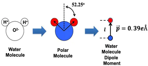
The dipole moment of the water molecule depends on the amount of charge transfer from the hydrogen to the oxygen (z*e), bonding angle, and the distance between the hydrogen and oxygen atoms. The dipole moment for the water molecule is given by:
From Eq.(1) we see that the strongest H-bond will occur when . The impact of an approaching water molecule has on such a H-bond is shown in Fig. 7 (for a material with relative dielectric constant ). A relative dielectric constant of was selected because of its usefulness when we discuss cell membranes in Section V.
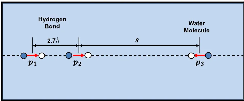
The potential energy of the charge distribution in Fig. 7 is given by:
In Fig. 8 we show what happens to the H-bond potential energy U as the water molecule approaches.
{"image_source":{"path":"images/0e9863c4f511bfe9ae3b224ec120c179fe7f0b4dedb2b55832e27e0d1823ae39.jpg"},"content":"","chart_caption":[{"type":"text","content":"Fig. 8: H-Bond breakage by an approaching water molecule."}],"chart_footnote":[]}
Fig. 8 shows that (for this material with relative dielectric constant ) H-bond weakening starts to occur when the water molecule is 10Å away and H-bond breakage occurs with the water molecule is Å away.
A water molecule in a dielectric material can easily generate very high local electric fields. This is the reason that water molecules are so effective in H-bond breakage, as illustrated in Fig. 9.
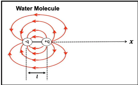
The potential at location x [in Fig. (9)] due to the dipole-charge distribution is:
The field at any location x (from the water-molecule dipole) is given by:
Thus, for a water molecule (with dipole charge of q = 0.39e and ) in a material of relative dielectric constant , the field at a distance of 2.5Å from the water molecule is approximately 15MV/cm. With this field, the H-Bond potential energy increase due the water molecule is
This increase in potential energy can serve to reduce the H-bond energy to zero. It can now be seen, regardless of whether we take a charge approach [Eq. (6)] or a field approach [Eq.(8)], we reach the same conclusion: a water molecule coming to within 2-3Å of a hydrogen bond can easily break the bond.
V. IMPACT OF EXTERNAL ELECTRIC FIELDS ON HUMAN CELLS
Electroporation refers to the application of external electric fields to induce pore formation in cell membranes. The creation of these pores typically leads to either necrosis (cell death) or apoptosis (irreversible cellular degradation). Although electroporation has been studied for over four decades, detailed physical models that fully describe the underlying mechanisms remain a subject of active research and interest. To optimize electroporation protocols, physics-based models are essential for quantitatively analyzing how variables such as pulse amplitude, frequency, and duration influence membrane disruption. More critically, from a molecular physics perspective, there remains a fundamental question: Which specific molecular bonds are being disrupted during the electroporation process?
This work introduces a self-consistent, physics-based model that focuses on the field-induced breakage of hydrogen bonds—key molecular interactions that are vital for maintaining the structural integrity of the cell membrane. The modeling approach draws heavily from reliability physics research in the semiconductor industry, particularly studies on time-dependent dielectric breakdown (TDDB), a long-standing issue in microelectronics. In both cases, bond degradation under electric stress is the central failure mechanism, providing a strong conceptual and mathematical bridge between biological and electronic systems.
For modeling purposes, the structure of a human cell is depicted in Fig. 10. The cytoplasm occupies the majority of the cell's volume and consists primarily of water with dissolved ions such as , , and . This region has a high relative dielectric constant of approximately . The nucleoplasm, comprising about of the total cell volume, has similar dielectric properties. The cell membrane, which is the primary focus of electroporation research, is a thin hydrophobic layer that encapsulates the cell. It functions as a selective barrier, permitting controlled ion transport while shielding the interior from external perturbations. Critically, this membrane has a much lower relative dielectric constant of and derives much of its mechanical and chemical stability from hydrogen bonding. The disruption of these H-bonds under an applied electric field is central to the electroporation mechanism explored in this study.
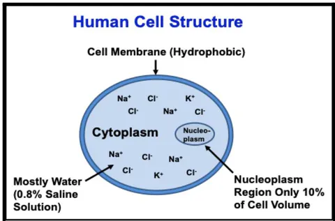
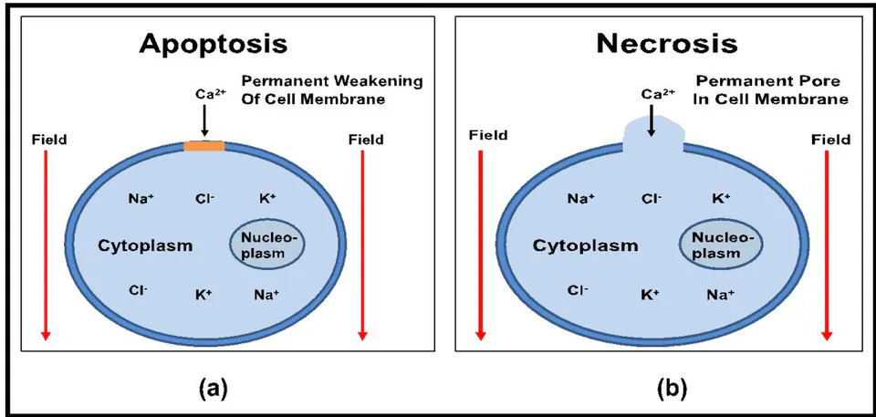
The cell membrane is relatively impermeable and protects the cell. However, pulsed electric fields can make the cell membrane permeable. Water molecule penetration into the membrane will cause rapid H-bond breakage leading to rapid cell membrane degradation. Electroporation is generally referred to as the use of pulsed electric fields to make the cell membrane more permeable. Pore formation in the cell membrane can lead to apoptosis (severe irreversible cell degradation) or to cell necrosis (cell death) as is illustrated in Fig. 11.
VI. CELL CAPACITOR DIELECTRIC MODEL
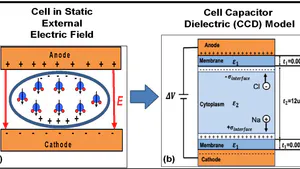
Figure 12 illustrates the primary components of the Cell Capacitor Dielectric (CCD) Model, which provides a simplified but insightful framework for understanding how electric fields interact with cellular structures. The model highlights three key elements:
Cytoplasm Region: This internal cell environment is composed of approximately 80% water and contains a variety of dissolved ions, primarily sodium (Na ), potassium (K ), and chloride (Cl ). Due to its high water content, the cytoplasm exhibits a high relative dielectric constant of approximately , making it highly responsive to electric fields.
Mobile Ions: These charged particles are free to move within the cytoplasm and play critical roles in maintaining membrane potential, signaling, and other cellular functions. Their distribution and dynamics are central to the cell's electrical behavior.
Cell Membrane: The membrane is a thin, hydrophobic dielectric layer surrounding the cytoplasm. It has a significantly lower relative dielectric constant of approximately and functions as both a protective barrier and a regulatory interface for ion transport. Structurally, the membrane is stabilized by hydrogen bonding, which is critically important for maintaining its integrity.
The hydrophobic nature of the membrane serves a crucial role—it prevents water molecules from penetrating and disrupting the hydrogen bonds within the membrane structure. As discussed earlier, these H-bonds are essential for membrane stability. If the dielectric layer is compromised, water molecules may infiltrate the membrane, leading to extensive H-bond breakage. This, in turn, can trigger necrosis or apoptosis, ultimately compromising cell viability.
By modeling the cell as a capacitor—with the cytoplasm and extracellular environment acting as conductive plates and the membrane as the dielectric layer—this CCD framework enables quantitative analysis of how external electric fields affect cellular function and stability. It also provides a physical foundation for understanding phenomena such as electroporation and dielectric breakdown in biological systems.
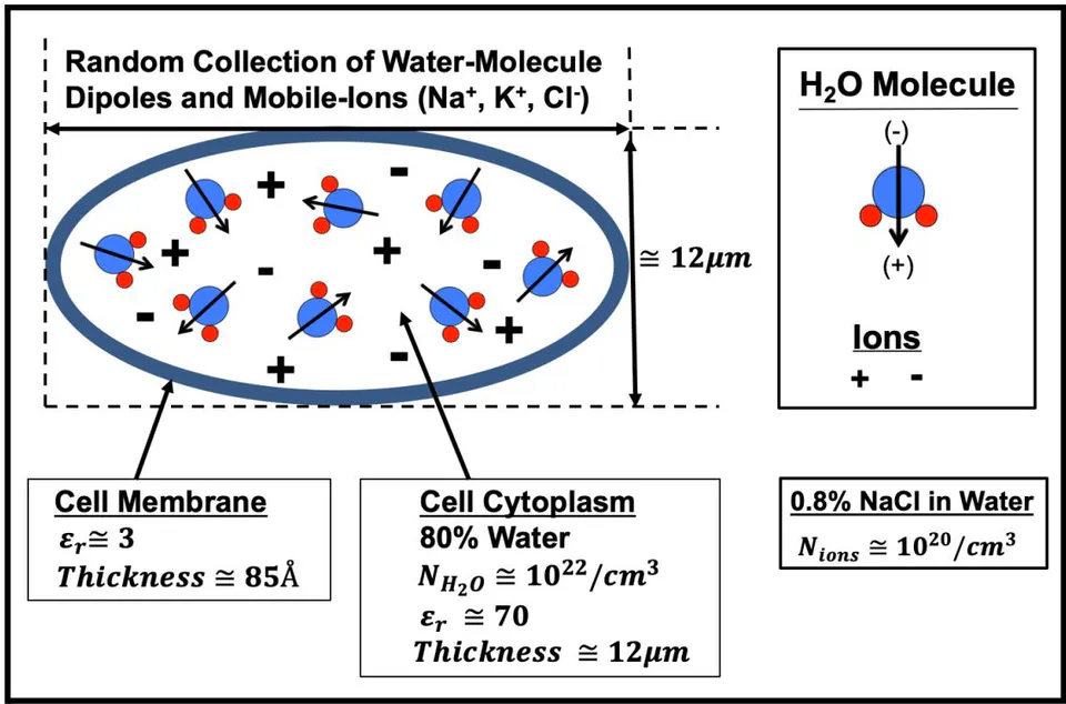
If an external electric field is applied to the cell shown in Fig. 12, the water-molecule dipoles will rotate and align with the electric field and the mobile-ions will drift with the electric field, as illustrated in Fig. 13.
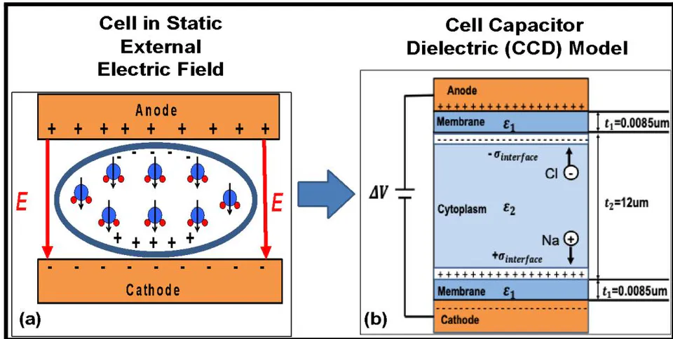
Fig. 13(b) illustrates the Cell Capacitor Dielectric Model (CCD-Model) used in this modeling effort to describe a human cell under an external electric field stress. In between the two metal electrodes, we show the cell cytoplasm ( 12um thick) and the cell membranes (each about thick). The cytoplasm is about water and its dielectric constant will be taken to be approximately since water molecules are very polar. Because the cell membrane is hydrophobic (little to no water molecules exist in this layer), the dielectric constant of the inner core of the cell membrane is taken to be .
In the CCD Model, if we ignore the mobile-ion drift for a moment, and use the fact that the electric displacement is continuous across dielectric interfaces, then the fields in each layer become
and
where the external field is defined as simply the voltage dropped a across the total dielectric thickness:
Using Eqs. (10) and (11), we see that, under static field conditions, the field in the membrane layer is 23.3 times greater than the field in the cytoplasm layer,
Any ion movement (due to the field and ions in the cytoplasm) will, of course, produce ion current and this current will lead to a charge buildup at the interface boundary between the cytoplasm and the membrane. This ion-charge buildup will lead to a further field increase in the membrane layer but reduced field in the cytoplasm layer, as given by:
and
The Na-ion and Cl-ion drift will continue in the cytoplasm layer until forces on the ions are balanced (by the tendency to drift due to the field in the cytoplasm versus the repulsive nature of like-charge building up at the interface). In steady-state, the equivalent but opposite forces on the ions of charge q becomes:
Eq.(16) [with the help of Eq. (11)] gives:
For example, at , the steady state interfacial charge buildup would be .
Finally, the field in each layer, due external field plus mobile-ion movement, is given by
and
One will recall that without mobile-ion movement, the field in the cell membrane was some 23.3 times greater than in the cytoplasm. With the Na and Cl ion drift (in the saline), the field in the membrane has increased to 71.3 times greater than the field in the cytoplasm. This means that in steady state, the expected degradation is most severe in the cell membrane.
As for how fast can the ions drift in order to establish the interface concentration of , the response time can occur within microseconds. This is because the actual drift distance is relatively short. With a 0.8% NaCl solution, there are Na and Cl ions present in the solution. Therefore, when a field is applied, if the Cl ions only drift 1Å away from the cathode (or Na ions drift only 1Å away from the anode), then this drifting leaves behind an enormous surface ion-concentration on the order of . This is more than enough to create the equilibrium ( ) .
The impact of a static external electric field on H-bonds will be quite different in each layer since the field in each layer is different. In the membrane layer, the field in this layer can be 70 times greater than the field in the cytoplasm layer. For this reason, we will focus our attention on the membrane. The reduction in H-bond strength in the membrane layer can be as great as,
To help comprehend the degrading impact of this reduction in H-bond energy has on human cells, it is instructive to determine a effective temperature-rise equivalent (TRE) for this amount of energy. TRE can be useful because we know that human cells degrade rapidly with only a few degrees rise in temperature. Since the average thermal energy of a vibrating molecule in a solid is , we can easily determine a TRE for the degrading impact of field in the membrane layer. We must remember that the TRE is not an actual temperature rise in the specimen but it is expected to have the same degrading impact at an actual temperature rise. The TRE is given by,
where is Boltzmann's constant equal to .
In Fig. 14, we show the TRE for various external fields. Note that some membrane degradation is expected at an external field of 1kV/cm. For an external field of 2kV/cm, the degrading impact of field on the cell membrane is expected to have the same degrading impact as if the cell temperature actually increased by 3°C. As a check on these results, remember that the homeostasis body temperature is 37°C (98.6°F). For a body temperature rise of 3°C (5.4°F), this would produce a body temperature of 104°F. A body temperature of 104°F (40°C) is considered a medical emergency, and prolonged exposure can lead to organ damage and death.
{"image_source":{"path":"images/29f0022e69dfe9e566108a4343ec1608f44ca457944130dea577eaaf5157c817.jpg"},"content":"","chart_caption":[{"type":"text","content":"Fig. 14: Impact of external fields on cell membrane degradation in terms of effective temperature-rise equivalents (TREs)."}],"chart_footnote":[]}
VII. IMPACT OF EXTERNAL FIELD ON HOMEOSTASIS FIELD IN MEMBRANE
Due to electrochemical differences between cytoplasm and extra-cellular region, an electric field exists in the membrane layer in its homeostasis (natural) state, as is illustrated in Fig.
Fig. 15: Illustrates the electric field that exists in the cell membrane in the homeostasis state.
| Extracellular Region | |
| Membrane ε1↓EHomeostasis | t1=0.0085um |
| Cytoplasm ε2 | t2=12um |
| Membrane ε1↓EHomeostasis | t1=0.0085um |
| Extracellular Region | |
The homeostasis voltage drop is generally accepted to be approximately 70mV. Thus, this voltage drop across the 85Å membrane layer produces a homeostasis field 82.4kV/cm. Therefore, when an external unipolar voltage is applied (as illustrated in Fig. 13), the field in the membrane layer near the anode will be higher:
The electric-field in the anode membrane is shown in Fig. 16. We can see that membrane damage is expected to start when the field exceeds 200V/cm.
{"image_source":{"path":"images/1b928b105cc0598f78e792f841719563c7f96135dc424657c0e9dfe7733127fd.jpg"},"content":"","chart_caption":[{"type":"text","content":"Fig. 16: Membrane potential versus applied external field. Little/no impact on homeostasis field in membrane for external fields "},{"type":"equation_inline","content":"\leq200V/cm"},{"type":"text","content":". Strong increases in membrane field above 200V/cm."}],"chart_footnote":[]}
VIII. IMPACT OF ELECTRIC-FIELD PULSING
As we have shown, the dielectric constants in the layers of a cell are critically important for determining fields in each layer because the cell degradation rate is expected to be strongly dependent on the field. The relative dielectric constant for a material depends on the polarization as given here:
where P is the dielectric polarization (net dipole moment per unit volume). There are various types of polarization, as illustrated in the Table shown. Polarization can occur via: electron cloud shifts, molecular bond-stretching, molecular rotation, and ion drift. Each polarization type has its own characteristic response time-constant. Polarization response-time physics is very important for a good understanding of the frequency dependence of pulsed-field testing of dielectrics.
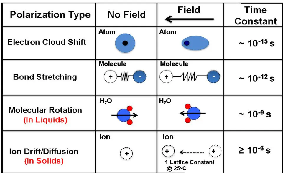
The observed polarization response times are not quite as sharp as the table would indicate. Due to many-body physical interactions in a material, a power-law frequency model has been demonstrated to be more useful in describing the observed frequency dependence in materials. This power-law dependence of is illustrated with a dashed line in Fig. 15.
{"image_source":{"path":"images/2ea425cc5055c82d3bef38e96a364dfff39da29c450c697eb7f7f1c23d8e9ccf.jpg"},"content":"","chart_caption":[{"type":"text","content":"Fig. 17: The general trend shown here is a reduction in dielectric constant "},{"type":"equation_inline","content":"\varepsilon_{r}"},{"type":"text","content":" with frequency."}],"chart_footnote":[]}
Due to many-body interactions in a solid, the observed dielectric constant (dashed line) takes on less of a lumpy appearance and more of an inverse power law dependence on frequency.
The impact of all of this physics on the cell response to pulsed electric fields can now be summarized. The cell membrane can more quickly respond to electric fields than the cytoplasm. Thus, for high frequency (GHz) pulsing, the cytoplasm will have a lower dielectric constant (due to the fact that the water molecules cannot rotate fast enough). This means that the cytoplasm layer will experience higher fields and the membrane lower fields. Since cell degradation is expected to be dependent strongly on field [Figs. 14 and 16], this would imply that GHz pulsing would be expected to induce more damage in the cytoplasm layer.
For lower frequency (MHz) pulsing, water molecule rotation should be nearly complete in the cytoplasm layer and this results in a higher dielectric constant and a lower field in this layer; but, as we have shown, the higher dielectric constant in the cytoplasm layer results in a much higher field in the membrane layer. Thus, MHz pulsing is expected to produce more damage in the cell membrane layer than in the cytoplasm layer. In summary, for electric-field pulsing, high frequency (GHz) pulsing is best for producing more damage to the cell cytoplasm region and less damage to the cell membrane. Lower frequency (MHz) pulsing produces more damage to the cell membrane layer and less damage to the cell cytoplasm region.
Before leaving this section on electric-field pulsing, perhaps we should again consider the cell membrane degradation model. Only those H-bonds anti-parallel to the field will experience an accelerated degradation rate due to an unipolar pulse. On average, 50% of the H-bonds will have some degree of anti-parallelism to the field and thus a higher degradation rate. In order for the field to have an adverse impact on the other 50% of the H-bonds, perhaps bipolar pulsing would be a more efficient way of pulsing for improved cell membrane electroporation.
IX. DISCUSSION
In this work, a physics-based model for hydrogen bond (H-bond) breakage in cell membranes was developed and presented. Electroporation was interpreted through the lens of dielectric breakdown, treating the cell membrane as the critical dielectric layer in a capacitor-like system. The Cell Capacitor Dielectric (CCD) Model introduced here conceptualizes a single human cell as a dielectric system, where irreversible membrane damage occurs when dielectric breakdown thresholds are exceeded. In a static external electric field, the cytoplasm—composed primarily of water—exhibits a high relative dielectric constant ( ), while the cell membrane's hydrophobic core has a much lower dielectric constant ( ). This disparity means that, under static or low-frequency electric fields, the electric field strength concentrates across the membrane, making it especially vulnerable to breakdown. The CCD-Model also demonstrates that the time-dependent dielectric properties of these cellular regions play a crucial role in determining the outcome of pulsed electric fields.
At lower-frequency pulsing (on the order of megahertz), water molecules within the cytoplasm have sufficient time to reorient and achieve full polarization. This results in a peak in the dielectric constant of the cytoplasmic region, which in turn reduces the local electric field within the cytoplasm and intensifies the field across the membrane. Additionally, ion drift (particularly of and ) induced by the electric field contributes to interface charging at the cytoplasm–membrane boundary. This further amplifies the membrane field, reinforcing the case for using MHz-range pulses in electroporation applications aimed at selectively targeting the membrane.
In contrast, at higher frequencies (in the GHz range), water molecules cannot fully reorient in response to the rapidly oscillating field. As a result, the dielectric constant of the cytoplasm decreases. This leads to an increased electric field in the cytoplasm and a relative reduction in the field across the membrane. Consequently, GHz pulsing is thought to produce more intracellular damage, potentially affecting the cytoplasmic and nucleoplasmic regions, including the nucleolus, rather than just compromising the membrane.
Finally, while this work is grounded in a purely physical modeling approach, it is important to recognize the need for cross-disciplinary efforts. For example, in the physical model presented, it was predicted and observed that external fields of will produce at least some cell membrane degradation. While a lower external-field electroporation process may not produce a stable pore (pore recovery is possible), this lower electric field may weaken the cell membrane to the extent that chemotherapy and/or immunotherapy is now much more effective.
X. Summary
A physical Cell Capacitor Dielectric (CCD) Model, based on hydrogen bond (H-bond) breakage, was presented to better understand the effects of external electric fields on cell membrane degradation. This model, which treats a single human cell as a capacitor with the membrane as the dielectric layer, effectively captures a wide range of observed electroporation behaviors. Whether the membrane damage is interpreted through an effective temperature-rise or a direct electric field-induced breakdown mechanism, the CCD-Model remains consistent with experimental data. It provides a unified explanation for varying degrees of cell membrane response across different electric field strengths. Specifically, the model predicts:
Minimal or no membrane damage at field strengths below 200 V/cm, aligning with Environmental Protection Agency (EPA) guidelines for exposure to high-voltage sources.
Initial, measurable degradation of the cell membrane at field strengths around 1 kV/cm.
Strong and irreversible membrane damage at approximately 10 kV/cm.
Catastrophic failure of the membrane at field strengths near 40 kV/cm.
These predictions are in good agreement with established electroporation data and widely accepted safety standards. In summary, the CCD-Model—grounded in the physics of hydrogen bond breakage—offers a useful framework for understanding how external electric fields can compromise cell membrane integrity. It provides insight not only into electroporation mechanisms but also into broader biomedical applications, potentially supporting future advances in therapeutic strategies involving electric-field exposure.
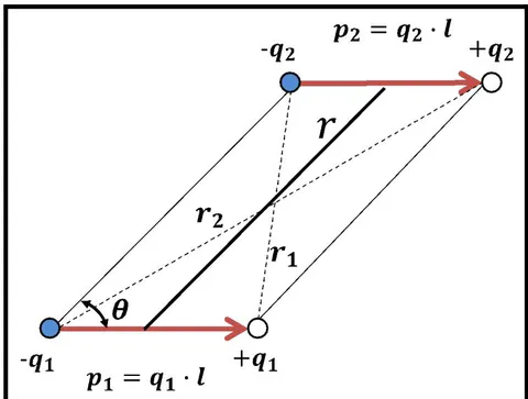
The potential energy of the charge distribution shown in Fig. A1 is given by:
Using the geometrical properties of the parallelogram,
where:
where:
Rewriting Eq. (A2) and expanding in a power series through quadratic terms, we obtain
Likewise,
Combining equations (A6) and (A7), we obtain
Therefore,
Conflict of Interest
The authors declare no conflict of interest.
Ethical Approval
Not applicable
Data Availability
The datasets used in this study are openly available at [repository link] and the source code is available on GitHub at [GitHub link].
Funding
This work did not receive any external funding.
References
Cite this article
Related Research

Special Issue
Launch a focused special issue to highlight research, emerging trends, and expert insights in your academic field.