


IntelliPaper
Abstract
Today, the sun is a very useful energy source because it continuously radiates energy. An electron is radiating energy continuously too. A new electrostatic generating method using this electron’s electric field energy as a driving force of charge carriers was invented,
and its success was presented on ESA 2017 and ESA 2019 by a bench model. This new electrostatic generator was realized by asymmetric electrostatic force, which is a new phenomenon. The electric output of the bench model was only a few ten micro-watt. Then, it is confirmed by a simulation that the electric output becomes kilo-watt when parts size is reduced to 1/100. However, the simulated machine can’t be manufactured actually because it’s a lot of charge carriers are very small and complex. But this problem has been solved by a new shape of the charge carrier and its new manufacturing method.
Explore Digital Article Text
I. INTRODUCTION
1.1 Two very useful energy sources: Sun and Electron
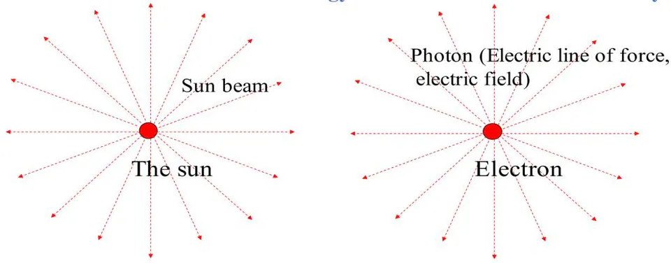
Today the most useful energy source to solve the environment problem is the Sun, because it is radiating a huge amount of energy around it continuously as shown in figure 1. Like the sun, an electron too is radiating an energy around it continuously. Of course, the radiated energy from an electron is very little. However, the number of electrons in our world is huge. An electret keeps an electron on its surface for a very long time (100 years). Therefore, if a new electrostatic generator is driven by an electret only, this one will solve the environment problem perfectly. Because it does not produce , it is safe, it produces electric energy all time everywhere, it has a long life time and its cost is low.
The sun and electron radiate energy all around direction continuously.
1.2 Asymmetric electrostatic force
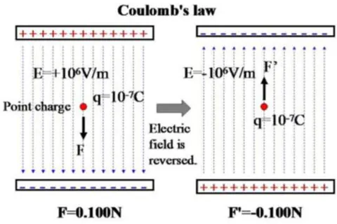
For a long time, the electrostatic force has been calculated by the well-known Coulomb's Formula (1).
It is apparent from this formula that the magnitude of this electrostatic force does not change when the direction of the electric field turns over as shown in Figure 2.
where f: Electrostatic force that acts on a point charge.
q: Quantity of a point charge.
E: Intensity of the electric field in which a point charge is placed.
The application of this formula is limited to point charges and sphere-shaped charge carriers [1].
A new electrostatic generator driven by only an electric field using Coulomb's law was tried for several years. Many different ideas were tested by a simulation and simple experiment.
However, a solution was not found, but a very useful phenomenon was found in those simulations by chance.
A new electrostatic generator driven by this new phenomenon was invented.
The electrostatic force that acts on an asymmetric charged conductor changes largely when the direction of the electric field reverses, as shown in Figure 3.
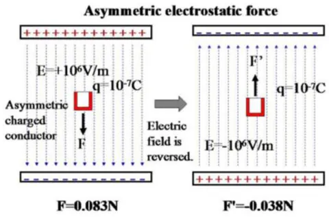
This new phenomenon was named asymmetric electrostatic force . The left side electric field of Figure 3 was named a forward electric field, and the right side electric field was named a backward electric field.
1.3 Basic theory of the new electrostatic generator
The basic theory of an electrostatic generator is defined by lifting the charge to a high potential by mechanical force against the electric force that It is impossible for the mechanical force to carry the charge directly. Therefore, the charge is packed into a suitable body. We call this body the charge carrier.
A basic unit of the new electrostatic generator that is driven by asymmetric electrostatic force is concretely shown in Figure 4.
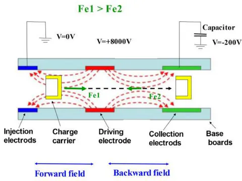
This generator mainly consists of a charge injection electrode, driving electrode, charge collection electrode, and charge carrier.
A positive high voltage was applied to the driving electrode. The injection electrode was grounded. The collection electrodes were kept at a negative low voltage.
As a result, the driving electrode and the injection electrode produced a forward electric field for a negative charge between them.
The driving electrode and the collection electrode produced a backward electric field for a negative charge between them.
A gutter-shaped conductor was used as a charge carrier that carries a negative charge (electron) from the injection electrode to the collection electrode through the driving electrode.
The asymmetric electrostatic phenomenon produces a large electrostatic force Fe1 in the forward electric field and a weak electrostatic force Fe2 in the backward electric field.
Therefore, the charge carrier gains large kinetic energy in the forward electric field. Then, it loses some of its kinetic energy in the backward electric field.
As a result, the charge carrier maintains extra kinetic energy when it arrives at the collection electrode.
The carried charge can be lifted to a higher potential by this extra energy.
This is the principle of the electric field-driven generator.
1.4 Experimental equipment of the electric field driven generator
Figure 5 shows the front view, Figure 6 shows a plane view and Figure 7 shows a photograph of the experimental equipment.
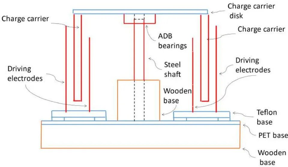
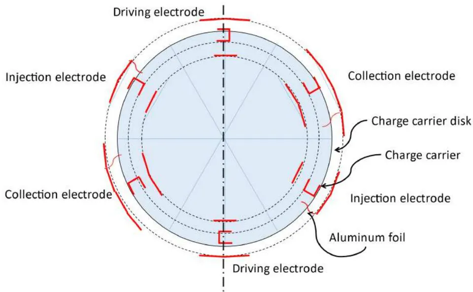
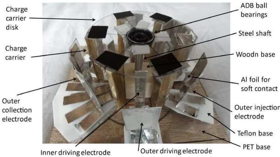
This equipment mainly consists of a charge injection electrode, a driving electrode, a charge collection electrode, and a charge carrier disk that has six charge carriers.
The charge carrier disk is a 0.5-mm thick PET plate with a diameter of 95 mm. ADB (autonomous decentralized bearing) bearings were fixed on the center of the disk.
The six charge carriers were placed at 60 degrees intervals, as shown in Figure 6.
The two charge injection electrodes, the two driving electrodes, and the two charge collection electrodes were placed on the main PET base plate at 60 degrees intervals, as shown in Figure 6.
The injection electrode was always grounded, the driving electrode was connected to a high voltage power supply, and the surface potential of the collection capacitor was measured by a surface potential meter.
The collection electrodes could perform semi-Faraday gauges. When the charge carrier was connected to the collection electrode by the aluminum foil, more than 90% charge on the charge carrier was transferred to the collection electrode (simulation result).
A surface potential meter (SHISHIDO ELECTROSTATIC: STATIRON-DZ 3) was used to measure the surface potential of the collection capacitor.
1.4 Experimental result of the electric field-driven generator
When -7kV was applied to the driving electrode, the charge carrier disk start to rotate automatically slowly. Then the rotation speed increase gradually, and it becomes constant finally. https://youtu.be/yNwOOTq3N-o. You can see this movie, when you click here.
This result indicates that the charge carrier disk can rotate endlessly by the electrostatic force against the air resistance force and kinetic friction force.
When the charge carrier continues to rotate, the surface potential of the collection electrode capacitor becomes higher in the negative direction. These results mean that this experimental equipment continued to endlessly generate electric power.
Figure 8 shows the surface potential change of the collection electrode capacitor when the driving voltage was 7.0 kV.
{"image_source":{"path":"images/b931283e0dfc9b3b57b30725bf49d4d50c78444bd412298de190366f1860b3ef.jpg"},"content":"","chart_caption":[{"type":"text","content":"Fig. 8: The surface potential change of the capacitor of the collection electrode for the rotation time of the charge carrier disk"}],"chart_footnote":[]}
This result was presented in ESA 2017 [9], [10], and an improved result was presented in ESA 2019 [11] using the new charging method shown in Figure 9.
{"image_source":{"path":"images/e4beef365382ee34d34cb7669f399cbb5e2653c6877d656242cf86f49104baf6.jpg"},"content":"","chart_caption":[{"type":"text","content":"Fig. 9: The improved charge injection method"}],"chart_footnote":[]} In Figure 9, the upper and lower side plates of the charge carrier and the injection electrode temporarily produce two capacitors. Therefore, many injection charges (electrons) are injected into the side plates from the ground through the electric connector.
The experiment of the new electrostatic generator succeeded many times after ESA2019. However, the success rate was not 100%. Therefore, the reason was researched and finally it became apparent that the result depended on the difference between the simulation and the real experiment [12], [13].
Any way, its electric output is only a few tens microwatt now.
1.5 Increasing Method of the electric output
1.5.1 Structure of the commercial machine
The experimental machine explained former has a big useless space under the charge carrier disk. Therefore, a commercial machine must lay the charge carrier down as shown in Fig.10.
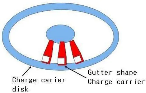
The injection electrode and the driving electrode on the experimental machine are changed to the injection electret and the driving electret on the commercial machine.
And also the injection electret, the driving electret and the collection electrode must be laid down too. They are placed face to face on back side of the upper electrodes disk and on surface side of the lower electrodes disk as shown in Fig.11.
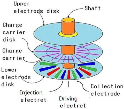
If the size of the charge carrier is like as the experimental machine, the radius of the disks become 90mm, and distance between the upper electrodes disk and the lower electrodes disk becomes 15mm.
This consist is named as 1 set. The size of 1 set become about same as CD cassette.
For high electric power, this set must be piled up as shown as Fig.12.
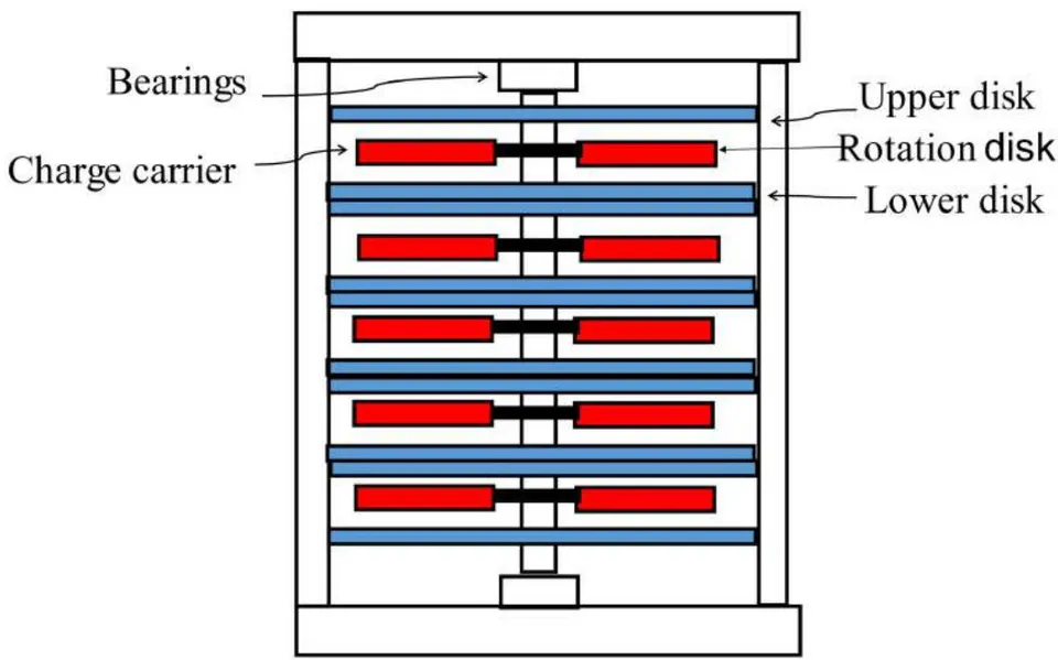
The upper electrodes disk and the lower electrodes disk are fixed to main body.
The charge carrier disk is fixed to center pole shaft and rotates with it. Fig.12 shows five sets piling structure. However, many sets can be piled on one ball bearings, because the weight of the charge carrier is very light (10g).
The rotation speed of the charge carrier disk of the experimental machine is about 100 rpm. However if air resistance that acts on the rotate charge carrier becomes zero by vacuum condition of the commercial machine, it will become several thousand rpm.
And if the ball bearings rotation is replaced of magnetic levitation rotation, the rotation speed will become several ten thousand rpm. As a result, very big electric power will be realized.
1.5.2. The methods that can increase the electrical output to one million times High speed rotation of the charge carrier disk
The rotation speed of the charge carrier disk of the bench model is about 100 rpm. However, The maximum rotation speed of the ADB ball bearings is 30,000 rpm. Therefore, when the rotation speed of the charge carrier disk become 10,000 rpm, the collected charge volume per seconds, namely a current becomes 100 times.
Increasing the charge density of the charge carrier When the charge carrier enters between the upper and lower charge injection electret, two air capacitors are produced temporally between the injection electret and the side plane plate of the gutter shape charge carrier.
At this time, the charge carrier is earthed. As a result, some charge is injected into the charge carrier. The polarity of this charge is reversal to the polarity of the charge on the injection electret.
The injected charge density is in direct proportion to the charge density of the injection electret and inverse proportion to the distance between the injection electret and the side plane plate of the charge carrier.
Now this distance is 7.5mm, namely 7500 m. Therefore, when this distance is reduced to 75 m as shown in Fig.13 (2), the injected charge density increases to 100 times.
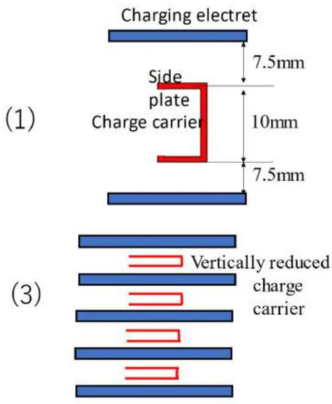
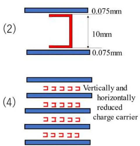
As a result, the collected charge volume per second, namely a current becomes 100 times.
Method of increasing volume charge density The height of the charge carrier was not related with the injection charge density. Therefore, the total volume charge of the all charge carriers become 100 times when the height is reduced from 10mm to 0.1 mm as shown Fig.13 (3).
However, width of the vertical reduced charge carrier becomes too long. Asymmetric electrostatic force can not pull this charge carrier. Therefore, the width must be reduced to 1/100 as shown in Fig.13 (4). As a result, total charge volume of the all charge carrier in the equipment becomes 100 times. Namely, the volume charge density becomes 100 times.
If multiply by those three methods, the electric output becomes times.
1.5.3 Simulation of the electric output increasing methods
Then the electric output of the field driven generator was simulated by finite difference method when the part size is reduced to 1/100. On the electrode disk, the size reduced injection electrets, the driving electrets and the collection electrodes are placed as shown in Fig.14.
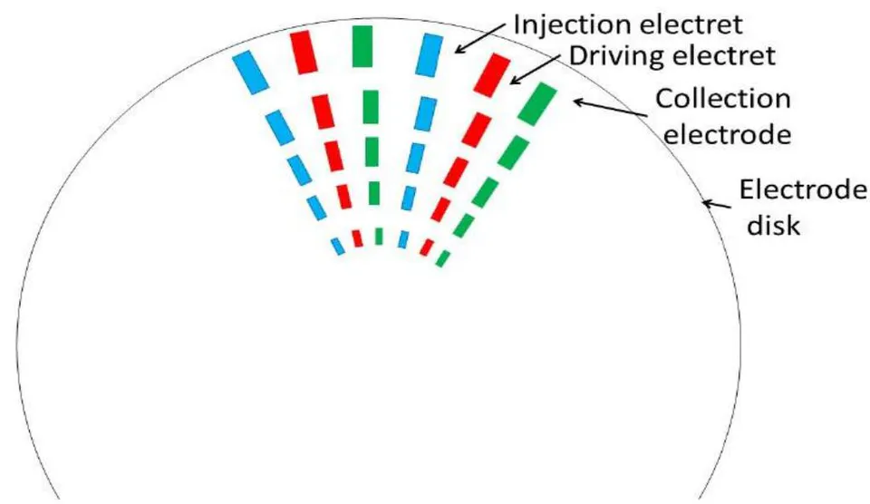
And on the charge carrier disk, the charge carriers are placed radially as shown in Fig.15.
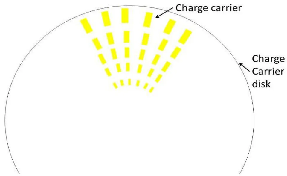
Table 1 shows the simulation condition of the first row on the charge carrier disk.
| Parts | Category | First row | Unit | |
| Thickness | 2 | μm | ||
| Charge carrier | Hight | 104 | μm | |
| Width | 102 | μm | ||
| Length | 600 | μm | ||
| Thickness | 8 | μm | ||
| Width | 160 | μm | ||
| Injection electret | Length | 600 | μm | |
| Charge density | 0.2 | |||
| Surface Potential | 180 | Volts | ||
| Parts | Thickness | 8 | μm | |
| Width | 64 | μm | ||
| Driving electret | Length | 600 | μm | |
| Charge density | 1 | |||
| Surface Potential | 900 | Volts | ||
| Thickness | 8 | μm | ||
| Collection electrode | Width | 192 | μm | |
| Length | 600 | μm | ||
| Surface Potential | 0 | Volts | ||
| Disk base plate | Thickness | 48 | μm | |
| One unit | Hight | 180 | μm | |
| Width | 1206 | μm | ||
| Injection distance | 10 | μm | ||
| Distances | Fe1 distance | 330 | μm | |
| Fe2 distance | 320 | μm |
The injected charge quantity and the electrostatic force that acts on this charged charge carrier was simulated by a two-dimensional finite difference method with table 1 conditions.
The injected charge quantity became -1.53e-11 [C] and the simulated electrostatic force is shown in Fig. 16.
{"image_source":{"path":"images/84aca8b36688b77f495aa7cc847628ce515cd7133cbd6ce96f0f914819e0236a.jpg"},"content":"","chart_caption":[{"type":"text","content":"Fig. 16: Distance from the injection electret ("},{"type":"equation_inline","content":"\mu m"},{"type":"text","content":")" and electrostatic force that acts on the charge carrier on first row"}],"chart_footnote":[]}
It is apparent from this graph that the forward force Fe1 is very strong and the backward force Fe2 is very weak. As a result, the large extra energy remains when the charge carrier arrives at the collection electrode. It was 1.21e-8 [J]. The carried charge quantity was -1.53e-11[C], therefore, this charge can be lift up to -794[V] by this extra energy.
One charge carrier transports -1.53e-11[C] when it traverse in the one unit. There are 250 unit on the first row. Therefore, when the charge carrier disk rotates one time, -3.79e-9[C] is transported to the collection electrode. There are 250 charge carrier on the first row, therefore, when the charge carrier disk rotates one time, -9.49e-7[C] is transported to the collection electrode. The rotation speed of the charge carrier is expected 10,000 rpm in the vacuum. Therefore it rotate 167 times in one second. As a result, -1.58e-4[C] is transported to the collection electrode in one second. Namely the current is -1.58e-4[A]. And the lifted voltage is -794[V]. Then the electric output of the first row becomes 1.26e-1[W].
The electrostatic force that acts on the charged charge carrier on the 33 row was simulated.
The electric output of the 33th row was simulated as 3.40e-2 [W], and the electric output of the second row to 32th row were calculated from the electric output of the first row and 33th row. As a result, Current, Voltage and electric output of the 1 set became -4.89e-3A, 538V and 2.63W respectively.
The height of the one set is 0.18mm. Therefore 555 sets can be packed into 100mm cubic box.
As a result, Current, Voltage and electric output of this 100mm cubic box generator became -2.71A, 538V and 1.46kW respectively [14].
This is a remarkable result, however the manufacturing of this machine is very difficult. There are the following five difficult points from the mechanical viewing.
The width of the charge carrier changes from 100 micrometers to 50 micrometers thirty-three times. Therefore, the manufacturing of those charge carriers becomes very complex.
The thickness of the charge carrier is too thin; it is only 2 micrometers. When the charge carrier passes between the driving electrets, a strong electrostatic force acts on it in the upper and lower directions. As a result, the shape of the thin charge carrier cannot be kept.
The rotation speed of the charge carrier disk is too fast; it is 10,000 rpm. The thin charge carrier will be destroyed by centrifugal force.
The distance between the injection electret and the side plate of the charge carrier is too narrow; it is only 10 micrometers. When the charge carrier disk vibrates slightly, they touch each other and the charge carrier will be crashed.
The width of the driving electret is too narrow; it is only 64 micrometers. A narrow-width electret is usually produced by a Teflon resin coating. However, less than 100 micrometers in width is difficult.
Therefore, the target of this paper is to solve the five problems and present the possible manufacturing method of the field driven generator.
II. POSSIBLE MANUFACTURING METHOD OF THE FIELD DRIVEN GENERATOR
2.1 The improved shape of the charge carrier and its manufacturing method
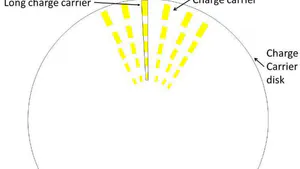
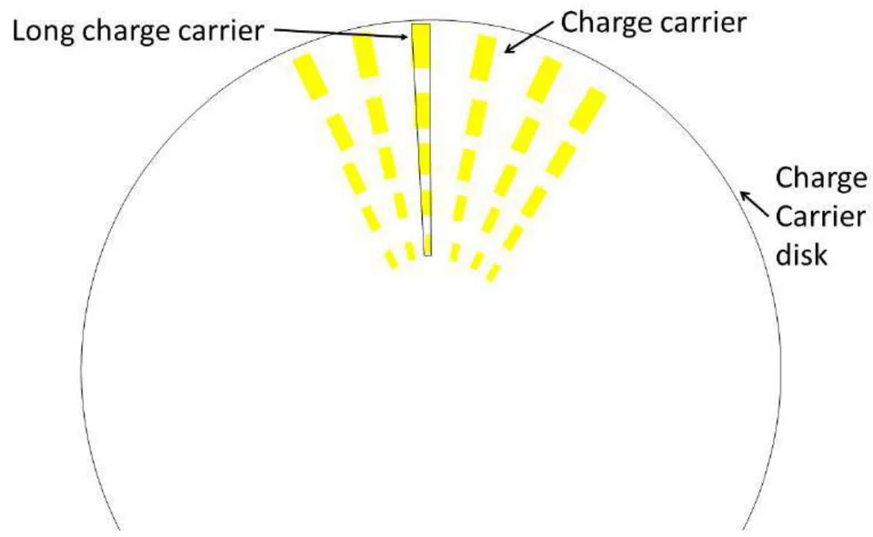
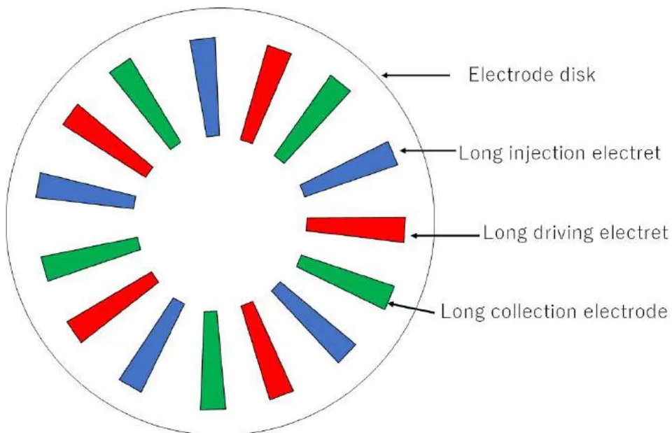
The manufacturing of thirty-three different width of charge carrier is very hard. Therefore, the thirty-three different width charge carriers were packed into one long charge carrier described as in fig.17. And the different width injection electret, driving electret and collection electrode were changed to long injection electret, long driving electret and long collection electrode.
Fig. 18 shows the new charge carrier disk that has long charge carriers and fig.19 shows the new electrode disk that has long injection electrets, long driving electrets and long collection electrodes. The above-mentioned problem 1 is solved with this long charge carrier.
The new charge carrier disk that has long charge carriers can be produced from one Aluminum circle plate. Because the shape of the long charge carrier is simple. At first, fig.19 shows the producing method when the width of the long charge carrier is constant.
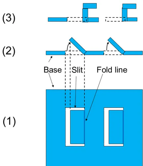
At first step, three slits are cut by laser beam on a thin Aluminum base plate and one-fold line is made as shown in fig.19 (1). Next, the three slits area is folded up as shown in fig.19 (2). Finally, this area is two times folded to right angle as shown in fig.19 (3).
As a result, side down gutter shape charge carriers have been made. This is a very simple production method of the charge carrier disk that has many long charge carriers.
Next, the manufacturing method of the charge carrier disk that has width changing long charge carrier is explained more concretely.
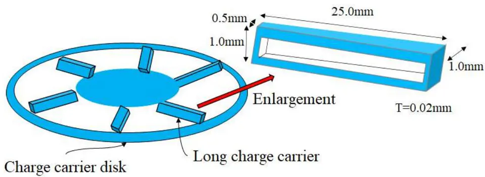
The width, the height, the thickness and the length of the long charge carrier was selected as 1.0 to 0.5mm, 1.0mm, 0.02mm and 25.0mm respectively as shown in fig. 20 for easy manufacturing.
{"image_source":{"path":"images/6b1fba99e89b45a2fef5b5ed43ed3549dc4dcc70ef436cef6a5de015130d07ef.jpg"},"content":"","chart_caption":[{"type":"text","content":"Figure 21 shows the manufacture method of this charge carrier disk."},{"type":"text","content":"Fig. 21: The explain figure of manufacturing of the width changing long charge carriers"}],"chart_footnote":[]}
The manufacturing methods consists of the following six steps.
Step 1: Preparing the base plate for the charge carrier disk. Its radius is 50mm and thickness is 0.02mm.
Step 2: The non-used areas are cut out as shown in fig.21. As a result, trapezoidal areas with sides 3, 25, 2.5, 25mm are remained.
Step 3: 3.0mm slit is cut at the upper side of the trapezoid and 2.5mm slit is cut at the lower side of the trapezoid. The slits are shown with red line in fig.21.
Step 4: Fold line 1 and fold line 2 are made on the trapezoid as shown in fig.21.
Step 5: The left area of the trapezoid is folded with fold line 1 perpendicularly to the base plate.
Step 6: The left of the folded area is folded with fold line 2. As a result, this area becomes parallel to the base plate.
This is a mechanically simple method. Therefore, a lot of charge carrier disk will be produced on line automatically.
And finally three charge carrier disks are piled with two thin non-conductive layers. The distance between the carriers on the different disk is kept 3.79 mm.
2.2 The electric output of the long charge carrier generator
The thickness of the charge carriers are increased from to for possible manufacturing. As a result, the above-mentioned problem 2 will be solved. However, its electric output will decrease. Now, the above-mentioned problem 1 and 2 are solved. However, problem 3, 4, 5 are remain. Therefore, the rotation speed of the charge carrier disk is reduced from 10,000 rpm to 1,000 rpm for solving the problem 3. The distance between the injection electret and the side plate of the charge carrier is expanded from to for solving the problem 4. And the width of the driving electret is expanded from to for solving the problem 5.
The size of all parts of the generator are enlarged with the above changing as shown in table 2
Those width are the size on the upper side of four trapezoid parts, namely the long charge carrier, the long injection electret, the long driving electret and the collection electrode. Those width reduce to half on the lower side of four trapezoid parts. For example, the width of the long charge carrier on the upper side is 1.0mm, however it reduces to 0.5mm on the lower side.
Simulation with changing the width gradually is impossible with two-dimension finite difference method. Therefore, this width is fixed at 0.76mm on the following simulation.
The results of the both simulation methods are expected about same.
Table 3 shows the simulation conditions with 0.76mm charge carrier.
| Parts | Category | Short carrier | Long carrier | Unit | |
| Thickness | 2 | 20 | μm | ||
| Charge carrier | Hight | 104 | 1000 | μm | |
| Width | 102 | 1000 | μm | ||
| Length | 600 | 25000 | μm | ||
| Thickness | 8 | 20 | μm | ||
| Width | 160 | 1500 | μm | ||
| Injection electret | Length | 600 | 25000 | μm | |
| Charge density | 0.2 | 0.1 | mC/m2 | ||
| Surface Potential | 180 | 225 | Volts | ||
| Parts | Thickness | 8 | 20 | μm | |
| Width | 64 | 600 | μm | ||
| Driving electret | Length | 600 | 25000 | μm | |
| Charge density | 1 | 1 | mC/m2 | ||
| Surface Potential | 900 | 2250 | Volts | ||
| Thickness | 8 | 20 | μm | ||
| Collection electrode | Width | 192 | 2000 | μm | |
| Length | 600 | 25000 | μm | ||
| Surface Potential | 0 | 0 | Volts | ||
| Disk base plate | Thickness | 48 | 500 | μm | |
| One unit | Hight | 180 | 1740 | μm | |
| Width | 1206 | 11360 | μm | ||
| Injection distance | 10 | 100 | μm | ||
| Distances | Fe1 distance | 330 | 3200 | μm | |
| Fe2 distance | 320 | 3200 | μm |
| Parts | Category | Short carrier | Long carrier | 0.76mm carrier | Unit | |
| Charge carrier | Thickness | 2 | 20 | 20 | μm | |
| Hight | 104 | 1000 | 1000 | μm | ||
| Width | 102 | 1000 | 760 | μm | ||
| Length | 600 | 25000 | 25000 | μm | ||
| Injection electret | Thickness | 8 | 20 | 20 | μm | |
| Width | 160 | 1500 | 1120 | μm | ||
| Length | 600 | 25000 | 25000 | μm | ||
| Charge density | 0.2 | 0.1 | 0.1 | |||
| Surface Potential | 180 | 225 | 225 | Volts | ||
| Driving electret | Thickness | 8 | 20 | 20 | μm | |
| Width | 64 | 600 | 480 | μm | ||
| Length | 600 | 25000 | 25000 | μm | ||
| Charge density | 1 | 1 | 1 | |||
| Surface Potential | 900 | 2250 | 2250 | Volts | ||
| Collection electrode | Thickness | 8 | 20 | 20 | μm | |
| Width | 192 | 2000 | 1600 | μm | ||
| Length | 600 | 25000 | 25000 | μm | ||
| Surface Potential | 0 | 0 | 0 | Volts | ||
| Distances | Injection distance | 10 | 100 | 100 | μm | |
| Fe1 distance | 330 | 3200 | 2400 | μm | ||
| Fe2 distance | 320 | 3200 | 2400 | μm | ||
| One unit | Hight | 180 | 1740 | 1740 | μm | |
| Width | 1206 | 11360 | 8650 | μm | ||
| Base plate | Thickness | 48 | 500 | 500 | μm |
The injected charge quantity to the charge carrier when it passes between the injection electret was simulated as -1.002 [nC]. Then the electrostatic force that acts on the charged charge carrier was simulated while the charge carrier reaves the injection electret and reaches to the collection electrode. Fig.22 shows the simulation result.
{"image_source":{"path":"images/8e0370b71a1767b652647202ff02cd9ddf676f79ea50532aae9afe18ac2b32c9.jpg"},"content":"","chart_caption":[{"type":"text","content":"Fig. 22: The electrostatic force that acts on the charge carrier with thickness 20 micro-meter"}],"chart_footnote":[]} In fig.22 the backward electrostatic force fe2 became positive when the charge carrier close to the collection electrode. This phenomenon happens depend on a strong image force. This unique phenomenon will be discussed on the next paper.
The extra energy was calculated as 1.445 [ J] from the electrostatic force shown in fig.22. As a result, the transported charge -1.00 [nC] was lifted up to -1445 [V] by this extra energy.
There are 81 charge carriers on the charge carrier disk and there are 27 units on the electrode disk, and the charge carrier disk rotate 16.7 times per second. As a result, the current of this generator became -3.65e-5 [A]. Namely, its electric output is 5.27e-2 [W] for one set.
The height of the one set is 1.74mm. Therefore, 57 sets were piled in 100 mm cubic box. Therefore, the electric output from 100 mm cubic generator became 3.00 [W]. And it became 3.00 [kW] for 1.0 m cubic generator. This generator will be useful for the non-electric area.
This generator will be useful even if its electric output became half.
Therefore, 40 and 60 micro-meter thickness charge carrier's electric output was simulated because 20 micro-meter Aluminum plate may be weak mechanically. The simulation condition of those two generators were the same without its charge carrier thickness as the simulation condition of the 20 micro-meter generator shown in Table.3.
The injected charge quantity of 40 micro-meter charge carrier became -1.007 [nC] and The injected charge quantity of 60 micro-meter charge carrier became -1.014 [nC] The simulated electrostatic force that acts on those charged charge carrier was shown in fig.23.
{"image_source":{"path":"images/c97839853558a917ee5fed4e05f0fad4606510617757227213593ea086620c19.jpg"},"content":"","chart_caption":[{"type":"text","content":"Fig. 23: The electrostatic force that acts on the charge carrier with thickness 20, 40, 60 micro-meter"}],"chart_footnote":[]}
The forward electrostatic force Fe1 that acts on the charge carrier with thickness 60 micro-meter was not simulated because the force is same as the force that acts on the charge carrier with thickness 40 micro-meter.
The voltage of the unit that has the 40 micro-meter charge carrier became -981 [V] and the voltage of the unit that has 60 micro-meter charge carrier became -797 [V].
As a result, the electric output of the 100 mm cubic generator that has the 40 micro-meter charge carrier became 2.04 [W] and the electric output of the 100 mm cubic generator that has the 60 micro-meter charge carrier became 1.67 [W].
Namely, the electric output of 1.0 m cubic generator that has 40 micro-meter charge carrier became 2.04 [kW] and the electric output of 1.0 m cubic generator that has 60 micro-meter charge carrier became 1.67 [kW]. a 40 or 60 micro-meter Aluminum plate may be stable mechanically.
However, more thickness may be required. Therefore, the electric output of the 1.0 m cubic generator that has 80 and 100 micro-meter charge carrier were estimated from the data of 20, 40,60 micro-meter charge carrier generator. Fig.24 shows the estimated electric output.
{"image_source":{"path":"images/9be2a680ffa7a8bff2d3bbb597d34e9e81fb11b375863ae69d10778eede6f85d.jpg"},"content":"","chart_caption":[{"type":"text","content":"Fig. 24: The estimated electric output for 1.0 m cubic generator that has 80 and 100 "},{"type":"equation_inline","content":"\mu"},{"type":"text","content":" m thickness charge carrier"}],"chart_footnote":[]}
The estimated electric output of 1.0 m cubic generator that has 80 or 100 m thickness charge carrier became 1.47 [kW] and 1.33 [kW] respectively. Namely the electric output of the 100 m thickness generator is less than half to that of the 20 m thickness generator. However if the rotation of the 100 m thickness generator is more stable than the rotation of the 20 m thickness generator, the rotation speed can be increased to 2000rpm or 3000rpm from 1000rpm, as a result its electric output becomes two or three times. And the injection distance can be reduced to 50 m from 100 m, as a result, the injected charge quantity becomes two times. Namely the electric output of the 100 m thickness generator becomes more than two times of the 20 m thickness generator.
III. CONSIDERATION
The electric output of the field driven generator that consists of thickness charge carrier is not large. However, it will be enough for erasing the non-electric area from the earth.
Of course, many problems must be solved for manufacturing it. One of them is a rotation mechanism of the charge carrier disk. We must select a suitable ball bearings. One of the suitable ball bearings is ADB (autonomous decentralized bearing) bearings invented by Mr. Kawashima [15]. Because the frictional main reason of a conventional bearings is the increase in slide friction between the balls and the retainer of the ball. ADB bearings make it so the loaded balls are not in contact with each other without using a retainer.
However, a magnetic levitation rotation may be used in the near future in place of a ball bearings.
The other problem is a narrow width electret. Many electret maker in Japan stopped to product an electret recently. However the following company continues to produce an electret and has an experience to made width electret.
TOHO KASEI CO.,LTD https://www.toho-kasei.co.jp/
IV. CONCLUSION
It can be expected that the commercial manufacturing of the field driven generator will become possible with the long charge carrier, its new manufacturing methods and the suitable parts size. The electric output of this field driven generator is now expected 1 ~3 [kW] for 1.0 meter cubic machine. However, the electric output will increase year by year with improving mechanical precision.
2. Does not generate .
3. Miniaturization is possible.
The parts required for manufacturing are common and the product cost is low.
Long life(the life of the electret is 100 years).
The output is stable.
No danger (during manufacturing, use, and disposal).
8. Lightweight.
- Directly connected power supply for each electric product, eliminating the need for power transmission lines and capacitors.
As its application, for example
Use in space where sunlight does not reach (beyond Jupiter).
Use inside the body where energy cannot be supplied from the outside, such as an artificial heart.
Electronic devices that need to be charged frequently, such as smartphones and PCs.
Power supply for radiotelephone relay stations. It can be installed on telephone poles without the need for solar cells or storage batteries.
Power supply for equipment (traffic signals, emergency guidance) required even during a power outage.
Conflict of Interest
The authors declare no conflict of interest.
Ethical Approval
Not applicable
Data Availability
The datasets used in this study are openly available at [repository link] and the source code is available on GitHub at [GitHub link].
Funding
This work did not receive any external funding.
References
Cite this article
Related Research

Special Issue
Launch a focused special issue to highlight research, emerging trends, and expert insights in your academic field.