

IntelliPaper
Abstract
Purpose: The main objective of the study is to investigate the shaft plane inclination caused by bendingmoments and torsional vibrations during rotation without considering tooth friction.
Methods: The law of vortex effects on gear vibrations was also considered. A four-degree-of-freedomstraight-tooth cylindrical gear dynamics model was developed based on the gyroscopic effect. ANSYSWorkbench was used to perform the model's finite element analysis, and Simulink was used for the simulationand analysis of the model.
Results: The gyroscopic effect is being investigated to determine the variation law of the intrinsic characteristicsofstraight cylindrical gears. The dynamic characteristics of straight cylindrical gears with and without gyroscopiceffects were compared, and the impact of gyroscopic effects on straight cylindrical gear systems was discussed.
Conclusions: Forward and backward vortex phenomena can be observed under the influence of the gyroscopiceffect, as the intrinsic frequency increases with rotational speed. The results show that the gyroscopic effect significantly affects the translational and torsional vibrations of the master/follower wheel. It has a moresignificant impact on the torsional vibration displacement of the master wheel and the translational vibrationdisplacement of the follower wheel.
Explore Digital Article Text
I. INTRODUCTION
In the context of the actual meshing process, straight-toothed cylindrical gears are not located in the centre. This is due to the presence of unevenness and other factors, as well as the gyroscopic effect. These factors result in the production of a large bending moment, which in turn leads to nonlinear characteristics of bending and torsion vibration coupling. In the context of high-speed operation, reliance on gyroscopic torque in gears gives rise to the occurrence of vortex phenomena. At speeds approaching the critical speed, transverse vibrations emerge, consequently resulting in severe alternating loads. This, in turn, ultimately leads to fatigue failure and damage to the transmission system. Therefore, the current protocol proposes a four-degree-of-freedom dynamics model of a straight cylindrical gear based on the gyroscopic effect without considering tooth friction based on the meshing coupling dynamics model of a typical straight cylindrical gear. Considering the translational degrees of freedom and bending moments in the y-direction, as well as the rotational degrees of freedom due to torsion, simulation, and analysis of the inherent characteristics and properties are performed. The dynamic response of a straight cylindrical gear was studied using the gyroscopic effect. The simulation results are then compared with the dynamic characteristics of a straight-tooth cylindrical gear without gyroscopic effect, and the impact of the gyroscopic effect on the dynamic characteristics of straight-tooth cylindrical gears is discussed.
Although many results have been achieved in the dynamic characteristics of gears in existing research, However, the neglect of bending moments and gyroscopic effects leads to the deviation of the model from the actual working conditions. Tugan Eritenel conducted a study on the three-dimensional non-linear vibration of a gear pair, elucidating the non-linear gear response using four parameters: the translational stiffness and torsional stiffness, acting on the centre of change of the stiffness position. The study did not take the torsional effect of bending moments into consideration, although it was founded on nonlinear gear response. O. Lundvall superimposed small displacement elasticity on the rigid body motion to model the dynamics of a straight-tooth cylindrical gear. Wang Feng et al. proposed a coupled bending-torsion-axis vibration model for helical gears based on the force and vibration displacement decomposition method, derived vibration differential equations for six degrees of freedom, and performed simulation calculations. Despite the establishment of a kinetic model by the studies of O. Lundvall and Wang Feng et al., the gyroscopic effect was not given full consideration. Cheng Yan-Li et al. developed coupled translational-torsional dynamics model of a straight cylindrical gear with tooth surface friction. They derived vibration differential equations in six degrees of freedom in a similar study. The vibration displacement of each gear was also determined using the Runge-Kutta method, as was the dynamic meshing force of the gear pair. In a similar study, Wang Li-Hua et al. developed a dynamic model of the bending-torsional-axial-torsional pendulum coupling vibration of the helical gear transmission system (comprising the helical gear, shaft and bearing). They derived the vibration differential equations with twelve degrees of freedom, calculated the vibration response of the transmission system, and performed three-dimensional finite element modal analysis. The study proposed by Zou Yu-Jing et al. broadly considered the effects of time-varying meshing stiffness, bearing stiffness, and friction on dynamic behaviour. Further, a 12-degree-of-freedom helical gear friction dynamics model based on load-sharing theory and kinetic and elasto-fluid lubrication theory was developed. The tribological properties and dynamic behaviour of tooth surfaces were developed, and the coupling between them was investigated. The dynamic characteristics of gears have been well presented in all the previous studies. However, some models consider the bending moment. Only the translation in the axial direction brought by the bending moment is considered during the bending moment, and the torsion caused by the bending moment is not considered, i.e., the inclination angle deviation of the meshing plane caused by the bending moment is overlooked. Therefore, the mechanical characteristics of the gears reflected in these models are different from the actual situation and cannot fully reflect the exact movement of the gears.
The majority of extant literature pertaining to the dynamic characteristics of straight-toothed cylindrical gears concentrates on the effects of time-varying meshing stiffness, tooth surface friction and other factors on the bending-torsion-axis coupling vibration. However, the following limitations must be noted: Although part of the study considered the axial translation brought about by the bending moment, the torsional effect caused by the bending moment was ignored, i.e., the bending moment led to changes in the inclination angle of the meshing plane, which could not fully reflect the actual state of motion of the gears. At high speeds, gears generate vortex phenomena due to gyroscopic moments. However, existing studies rarely incorporate the gyroscopic effect into their models, resulting in an inability to accurately describe the dynamic characteristics of gears under high-speed rotation. Existing two-degree-of-freedom or four-degree-of-freedom vibration models do not take into account the influence of bending moments, which differ from the actual situation and cannot truly reflect the dynamic characteristics. The objective of this paper is to address the limitations of existing models in accounting for bending moment and gyroscopic effect. The present study considered the relationship between the law of vortex motion and gear vibration. A four-degree-of-freedom straight-tooth cylindrical gear dynamics model based on the gyroscopic effect is established to study the dynamic characteristics under the gyroscopic effect. Further, the dynamic characteristics of the gyroscopic effect were compared without the gyroscopic effect. Owing to the complexity of gear operating conditions or the unknown nature of specific failure mechanisms, it is necessary to investigate the dynamic characteristics of straight cylindrical gears by developing a dynamic model that takes gyroscopic effects into account during the dynamic design phase of actual gear systems, which is critical for the practice of rotor dynamics design and analysis of actual rotating machinery.
The present study improves the theoretical system of the study on the dynamic characteristics of straight-toothed cylindrical gears, provides a more accurate reference for the design and analysis of rotor dynamics of actual rotating machinery, and helps to improve the reliability and stability of the gear transmission system, and avoids fatigue failures and damages due to the inaccurate analysis of the dynamic characteristics.
II. MATERIALS AND METHODS
The gear and shaft system used in this study is made of high-strength alloy steel, a material widely used in high-speed rotating machinery for its excellent mechanical properties and wear resistance. Tables 1 and 2 list the main parameters of the gear. However, due to design, manufacturing and construction errors, the centre of mass of all actual rotors is more or less offset from the axis of rotation, resulting in dynamic imbalance of the gears. This dynamic imbalance gives rise to a deviation of the centre of mass from the two support centres, thereby triggering complex dynamic behaviour.[8] In high-speed gear shaft systems, transverse deformation of the rotating shaft occurs when it is subjected to external disturbances or its own unbalanced moments. This deformation results in a deviation of the geometric centre line of the shaft from the bearing centre line. In this case, the gear-axis system undergoes two distinct motions. Firstly, it rotates at high speed around a fixed axis, extending from the deviated axis. Secondly, the deformed rotor shaft executes a spatial slewing motion around the original static equilibrium axis. The combination of these two rotations results in the formation of the vortex phenomenon. This vortex phenomenon becomes more and more significant as the rotational speed increases, especially under high-speed operating conditions, where the gyroscopic effect further exacerbates the generation and complexity of vortices.[11] The present study proposes a mathematical model based on multi-body dynamics, the purpose of which is to facilitate a comprehensive investigation into the influence of gyroscopic effect and dynamic unbalance on the dynamic characteristics of gears. The model incorporates a series of elements, including the meshing characteristics of the gears, the elastic deformation of the rotating shaft, and the gyroscopic effect. The mass, stiffness and gyroscopic matrices of the system are obtained through the process of discretising the gear and shaft system by means of the finite element method. It is evident that the experimental conditions imposed on the study rendered it incapable of validating the model through experimental means. However, in order to ensure the reliability and accuracy of the developed model, the theoretical correctness of the model was verified by comparing it with the classical theory.
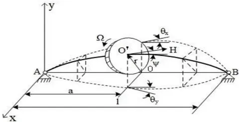
When the disc is not mounted in the center of the two supports but is preloaded to one side, as shown in Figure 1, it is preloaded on support A. When the rotating shaft deforms during movement, the figure depicts the shaft as curved. The axis of the disc makes an angle with the line connecting supports A and B at this point.
The disk has two motions at that time: one is the rotation of the disk around its center, and the other is the rotation of the disk's center O' and the two supports A and B formed by the plane around the two-support line AB to make a circular motion which is known as the whirling motion. It is evident that, consequent to the motion, the momentum H of the disc will undergo perpetual alteration in direction, thereby engendering a moment of inertia, otherwise designated as the gyroscopic moment, which is the moment at the preloaded disc acts on the axis of rotation.
If the influence of rotating torque in the rotor structure is not significant, the difference between the intrinsic frequency and the critical speed in the modal analysis may not be significant. Nonetheless, in the context of rotor dynamics analysis, given that the gear wheels are not situated at the centre, the meshing surface is inclined at a specific angle as a consequence of the bending torque. This results in a change in the inclination angle with the bending torque, leading to a change in the mechanical characteristics; thus, it is necessary to consider the spinning torque.
As shown in Fig. 1, the gyroscopic moment is considered, and the differential equations of motion of the disc can be obtained by combining the centre of the mass theorem, as shown below [9]:
Typically, the respective stiffness coefficients have the following relationships for a single-disk rotor system with a circular cross-section of the rotor shaft.
If the disc is mounted at the midpoint of the two supports, i.e., at a =l/2, the bending deformation equation provides the respective stiffness coefficients as follows:
Thus, the differential equation of motion for the gear considering the gyroscopic effect can be derived:
Where E is the modulus of elasticity of the material (steel); I is the cross-sectional moment of inertia of the rotating shaft; l is the span of the rotating shaft; is the diameter rotational moment of inertia; H is the momentum moment of the disc.
III. MODELLING OF DYNAMICS CONSIDERING GYROSCOPIC EFFECTS
3.1 Gear Structure and Parameters
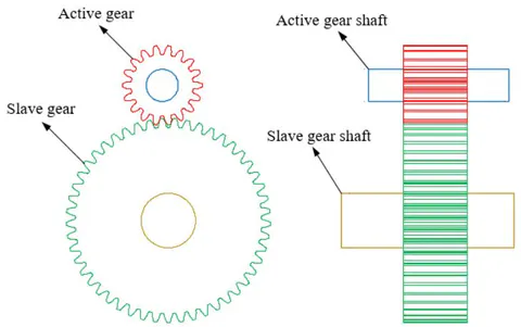
Figure 2 depicts the structure of the straight cylindrical gear used in this paper, and Tables 1 and 2 list the main parameters of the gear.
| Parameters | Active Wheel P | Slave Wheel G |
| Base circle radius/(m) | 0.009 | 0.025 |
| Mass/(kg) | 0.048 | 0.422 |
| Tooth number | 18 | 49 |
| Modulus/(mm) | 1.25 | |
| Tooth width/(m) | 0.02 | |
| Pressure angle/(°) | 20 | |
| Input torque/(N·m) | 1 | |
| Gear rotation inertia Iz/(kg·m2) | 3.75e-6 | 2.13e-4 |
| Engagement stiffness Km/(N·m-1) | 1.57e8 | |
| Engagement damping Cm/(N·s·m-1) | 157 |
| Parameters | Active wheel P | Slave wheel G |
| The cross-sectional diameter of the gear shaft/(m) | 0.01 | 0.017 |
| Span of the gear shaft/(m) | 0.044 | 0.054 |
| Cross-sectional moment of inertia of gear shaft/(m4) | 4.91e-10 | 4.1e-9 |
| Elastic modulus/(N·m-2) | 2.06e11 |
3.2 Dynamical Modeling
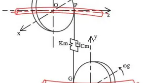
The study describes the elasticity of the drive shaft and support bearings, but does not consider tooth friction. Furthermore, a gyroscopic effect-based dynamics model of the straight cylindrical gear was developed. The meshing coupling type dynamics model of the straight cylindrical gear pair is shown in Fig. 3.
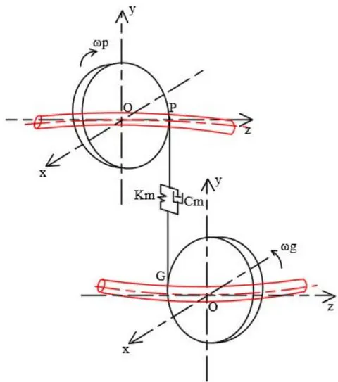
Without considering the surface friction of the gear teeth, the dynamic meshing force of the gear teeth acts in the direction of the meshing line. Consequently, the model demonstrated four degrees of freedom. The vibration displacement of these four degrees of freedom is represented by , , , , where and denote the translational vibration displacement of the central and driven wheel centre point in the y direction, and and represent the torsional vibration displacement of the central and driven wheel centre point. The generalized displacement array of the system can be expressed as follows:
Suppose the displacements of points P and G along the y-direction in Figure 2 are yp' and yg', respectively. In that case, the relationship between them and the system vibration displacement can be expressed as [10]:
Further, the elastic meshing force and viscous meshing force between the meshing wheel teeth can be expressed as :
and
Km and Cm are the integrated stiffness and damping of the gear pair mesh, respectively.
Therefore, the dynamic tooth meshing forces and acting on the active and driven wheels can be represented:
According to the above analysis, the analytical model of the system can be deduced as:
Where mi, are the masses of the primary and driven gears and the moment of inertia of the cross-section and expressed as shown below:
In the matrix form, the analysis model table can be follows:
IV. RESULTS AND DISCUSSION
4.1 Inherent Characteristics
In order to solve the finite element model of straight-toothed cylindrical gears, it is necessary to take into account the gyroscopic effect. The gyroscopic effect is defined as an inertia effect that arises from the conservation of angular momentum of a rotating object. This effect is indicative of the influence of the angular velocity of the rotating parts on the dynamics of the system, and thus plays an instrumental role in the analysis of rotating systems. Within the ANSYS Workbench, the gyroscopic effect is realised through the incorporation of the gyro matrix, which is then subjected to analysis via the Campbell plot. In ANSYS Workbench, the finite element model of a straight-toothed cylindrical gear focuses on the effect of its mass distribution on the dynamic characteristics by simplifying the gear to a mass (Point Mass), while the gear shaft is simulated using a higher-order beam cell (e.g., BEAM 188 or BEAM 189) to efficiently capture the bending and torsional deformation characteristics of the shaft. In the process of mesh generation, the mesh density is optimised according to the geometry of the axes and the stress distribution. This ensures sufficient mesh accuracy in critical areas. The boundary conditions are defined as simple support constraints at both extremities of the gear shaft. This type of constraint has been demonstrated to be superior in simulating the support conditions in actual engineering scenarios and reflecting the dynamic characteristics of the shaft system. The mass distribution of the system as a whole is primarily concentrated in the gear component, and the mass and moment of inertia of the gear are simulated by Point Mass. In the course of the simulation process, the aim is to simplify the model and enhance the computational efficiency.
In order to achieve this, the following assumptions are made:
The gear and shaft materials are taken to be uniform isotropic materials.
In the preliminary analysis, the friction and lubrication effects in the gear meshing process are not taken into account.
{"image_source":{"path":"images/196a439ac326fc7ff6d4cf7ab8c86ce6a641833ec1141feb9b758c30d9191820.jpg"},"content":"","chart_caption":[],"chart_footnote":[]} {"image_source":{"path":"images/5b1667b24fee1d4bb75751f86784a1cf32738692d5a44286b52bc20e17f27830.jpg"},"content":"","chart_caption":[{"type":"text","content":"(b)"},{"type":"text","content":"Fig. 4: Campbell Diagram of Active and Slave Gear"}],"chart_footnote":[]}
The results of the Campbell diagram calculations for the master and driven wheels are shown in Figure 4. The Campbell diagram for the active wheel P is displayed in Figure 4(a), and the Campbell diagram for the slave wheel G is displayed in Figure 4(b). The inherent frequency increases with speed in the figure, and the phenomenon of the forward and backward vortices can be seen, as the shaft of the high-speed gear has a rotationally symmetrical structure. When the rotational speed is 0, there are only two types of oscillations with different phases of the same inherent frequency order. The gyroscopic effect produces a reverse vortex frequency below the intrinsic frequency of the structure and a forward vortex frequency above the intrinsic frequency of the structure as the shaft rotates. The higher the velocity, the more pronounced the bifurcation.
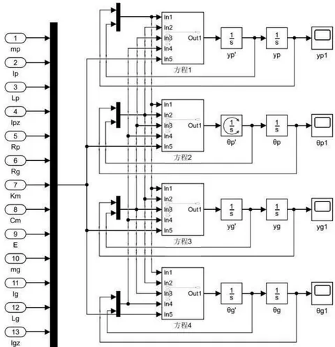
constructed subsystems via signal lines. The subsystem solution was integrated using the continuous integration module, and equation (15) was derived. By setting the simulation computation time to 10s, ode45 (Runge-Kutta) was chosen as the solver for iterative integration. As shown in Figure 5, the structural diagram of the straight cylindrical gear Simulink simulation model was created following the above steps.
4.2 Dynamic Response
Simulink simulation of a straight cylindrical gear dynamics model using the straight cylindrical gear parameters shown in Table 1. The time-varying meshing stiffness was replaced with the equivalent meshing stiffness. The model was created using a set of equations (10), which includes 13 known variables and 4 unknown variables. The subsystem module was used to construct the subsystems of equations (11) to (14) and the known variables connected to the four
The dynamic characteristics of straight tooth cylindrical gears with and without gyroscopic effect are compared and analyzed, and the simulation results are shown in Figs. 6 to 9.
{"image_source":{"path":"images/48116b261570dfbfe6ee513d3a38813af2ea12c3a107b7d1896030fa106c6fcd.jpg"},"content":"","chart_caption":[],"chart_footnote":[]} {"image_source":{"path":"images/3614f8a095cc0fa83757b17217e11f6555a3dbe02ccbdc1ce607d9cb7b60733e.jpg"},"content":"","chart_caption":[{"type":"text","content":"(a) Consider the gyroscopic effect"},{"type":"text","content":"(b) Disregard the gyroscopic effect"},{"type":"text","content":"Fig. 6: Variation curve of active wheel translational vibration displacement with time"}],"chart_footnote":[]}
{"image_source":{"path":"images/6b3e5520f619ed76769fad01aa838faf4fea736094e5cee6a5d39fb3eb3329f7.jpg"},"content":"","chart_caption":[],"chart_footnote":[]} {"image_source":{"path":"images/0799b494cedaf178eec2b4a5cd9887c48874e7d731ab0c396801182c76579b3a.jpg"},"content":"","chart_caption":[{"type":"text","content":"(a) Consider the gyroscopic effect"},{"type":"text","content":"(b) Disregard the gyroscopic effect"},{"type":"text","content":"Fig. 7: Variation Curve of Slave Wheel Translational Vibration Displacement with Time"}],"chart_footnote":[]}
Fig. 6 represents the variation curves of the translational vibration displacement of the active wheel with time. In contrast, Fig. 7 shows the variation curves of the translational vibration displacement of the driven wheel with time. Figs. 6(a) and 7(a) illustrate the waveforms of translational vibration displacement considering the gyroscopic effect. Figs. 6(b) and 7(b) show the waveforms of translational vibration displacement without the gyroscopic effect.
It is possible to comprehend the influence of gyroscopic effects on the translational vibrational displacement of the system by comparing Figures 6(a) and 6(b). In Fig. 6(a), the translational vibration displacement of the gear remained relatively constant in the vibration amplitude during the first 2s of simulation time. The vibration amplitude increased significantly after the system worked for 2s, with a change of . However, the fluctuation of the vibration amplitude was relatively smooth. In Fig. 6(b), the translational vibration displacement of the gear varied in the range of to with a variation of .
Although the translational vibration displacement of the gear appeared small in the system without the gyroscopic effect, the fluctuations in vibration amplitude are more prominent.
The comparison of Figs. 6(a) and 7(a) shows that the amplitude of the master/follower wheel's translational vibration displacement does not change significantly during the first 2 sec of simulation time. However, after 2 s of system operation, the translational vibration displacement of the master wheel changed in the range of mm to mm with a variation of mm. The translational vibration displacement of the driven wheel varied from mm to mm with a variation of mm. The result revealed that the gyroscopic effect greatly influenced the translational vibration displacement of the driven wheel.
{"image_source":{"path":"images/cf2e29077f6c4713822c7d5d4d56605896ec91abc12cf4b84f616195071868b7.jpg"},"content":"","chart_caption":[{"type":"text","content":"(a) Consider the gyroscopic effect"}],"chart_footnote":[]} {"image_source":{"path":"images/1e341d5c4960927b32822a3339ac1fe9714ca95ea287045f5305bc220766d206.jpg"},"content":"","chart_caption":[{"type":"text","content":"(b) Disregard the gyroscopic effect"}],"chart_footnote":[]}
{"image_source":{"path":"images/79d0ce6eba27f026d41e125ce030c4e122b43ac3ff97fd7f819db54e135c69de.jpg"},"content":"","chart_caption":[{"type":"text","content":"Fig. 8: Variation Curve of Active Wheel Torsional Vibration Displacement with Time"}],"chart_footnote":[]} {"image_source":{"path":"images/5545ac69047e11a4aa80b8178f39c16287c930d8139071f3f415a99421d72f65.jpg"},"content":"","chart_caption":[{"type":"text","content":"(b) Disregard the gyroscopic effect"},{"type":"text","content":"Fig. 9: Variation Curve of Slave Wheel Torsional Vibration Displacement with Time"}],"chart_footnote":[]}
Fig. 8 shows the variation curve of the torsional vibration displacement of the active wheel with time, and Fig. 9 shows the variation curve of the torsional vibration displacement of the driven wheel with time. Figs. 8(a) and 9(a) depict the waveforms of torsional vibration displacement considering the gyroscopic effect. In contrast, Figs. 8(b) and 9(b) show the waveforms of torsional vibration displacement without considering the gyroscopic effect.
The comparison of Figs. 8(a) and 8(b) demonstrate the gyroscopic effect on the torsional vibration displacement of the system. In Fig. 8(a), the torsional vibration displacement of the gear rises rapidly in the first 2s of simulation time, and the vibration amplitude tends to stabilize after 2s of system operation. The displacement of the vibration varies between 3 rad. The torsional vibration displacement of the gear varied from -0.03 rad to 0.01 rad with a variation of 0.04 rad, as shown in Fig. 8(b). Although the amplitude of the torsional vibration displacement of the gear is small in the absence of the gyroscopic effects, the fluctuations in the vibration amplitude was more pronounced.
The comparison of Figs. 8(a) and 9(a) further reveal that the torsional vibration bits of the master/follower wheel changed linearly and rapidly during the first 2 s of simulation time. After 2 s of system operation, the torsional vibration displacement of the master wheel fluctuated up and down around 3 rad. Notably, the torsional vibration displacement of the follower wheel fluctuated up and down around 1.1 rad. The result suggests that the gyroscopic effect significantly impacts the torsional vibration displacement of the active wheel.
Since the rotor vortex motion is caused by the dynamic deformation of the rotor shaft, the rotor shaft will change from static deformation to dynamic deformation at some point during the gear rotation. The static deformation is minimal and the gear motion's effect is negligible. It can therefore be deduced that the gyroscopic effect is only affected following two seconds of system operation.
V. CONCLUSION
In this study, a four-degree-of-freedom straight cylindrical gear dynamics model based on the gyroscopic effect is established, and the influence law of the gyroscopic effect on the gear vibration is analysed. The analysis showed that, when the gyroscopic effect was considered, the amplitude of the translational vibration displacement change of the master wheel is mm, and the maximum magnitude of the torsional vibration displacement is 3 rad. In contrast, the amplitude of the translational vibration displacement change of the follower wheel is mm, and the maximum magnitude of the torsional vibration displacement is 1.1 rad. In the absence of consideration for the gyroscopic effect, the translational vibration displacement of the master/follower wheel varies by mm, and the maximum magnitude of the torsional vibration displacement is 0.03 rad. The results show that the gyroscopic effect has a significant effect on the transverse and torsional vibrations of gears, a finding of great importance for the study of gear dynamics. In practice, understanding the mechanism of the gyroscopic effect helps to optimise gear design, improve gear life and reduce vibration, thus improving the overall performance of the mechanical system. For example, in a high-speed rotating gear transmission system, consideration of the gyroscopic effect can more accurately predict the dynamic behaviour of the gears, thereby optimising the structural parameters and operating conditions of the gears, reducing vibration and noise, and improving the reliability and efficiency of the system.
However, there are some limitations to this study. For example, the model made simplifying assumptions about the material properties and contact conditions of the gears and did not consider the effect of lubrication conditions on the dynamic characteristics. In addition, studies have mainly focused on straight cylindrical gears, and the influence of gyroscopic effects on other types of gears, such as helical cylindrical gears or bevel gears, has not yet been addressed.
Future research can be carried out in the following aspects: firstly, the model can be further improved to take into account more actual working condition factors, such as lubrication and tooth wear, in order to improve the accuracy and applicability of the model; secondly, the object of research is extended to study the difference in dynamic characteristics of different types of gears under the influence of gyroscopic effect; thirdly, in combination with experimental verification, the theoretical model and design method are further optimised by comparative analysis of actual test data and numerical simulation results.
Author Contributions
Conceptualization, Lifeng Chen; Resources, Mingjun Wang; Writing and Editing, Pengpeng Xu.; Review Lifeng Chen.; Funding Acquisition, Pengpeng Xu.
Funding
A Project Supported by Scientific Research Fund of Xiangtan Institute of Technology (2023YB23)
Conflicts of Interest
The authors declare no conflict of interest.
Conflict of Interest
The authors declare no conflict of interest.
Ethical Approval
Not applicable
Data Availability
The datasets used in this study are openly available at [repository link] and the source code is available on GitHub at [GitHub link].
Funding
This work did not receive any external funding.
References
Cite this article
Related Research


Special Issue
Launch a focused special issue to highlight research, emerging trends, and expert insights in your academic field.