



IntelliPaper
Abstract
Staircases connect the floors of multi-storey buildings and pedestrian bridges. There are different types of stairs, such as straight stairs, straight stairs with intermediate landings, curved stairs, L-shaped stairs, etc. The study focused on straight staircases with a central beam supporting the stairs as a double cantilever. The study of structural systems is relatively rare. There are four loading cases that we examine; the first is a live load on one side of the staircase, the second is a live load on both sides of the staircase, the third is a time history of three earthquakes, and the fourth is a dynamic load of pedestrians. A major objective of this study was to establish equations for estimating the central beam's internal forces.
Explore Digital Article Text
I. INTRODUCTION
Stairs are a critical topic in structural engineering, as they provide access between floors, whether in public markets, residential buildings, government departments, or pedestrian bridges. This is a brief overview of the history of stairways as they relate to different civilizations, architectural ideas, and structural designs. Wood trunks formed the stairs approximately 6000 years ago. Scientists discovered the first granite staircase leading to the sacred mountain in Tai Shan, China, and the spiral staircase in the Babel Tower, as well as screws stairs used for military purposes in castles, and straight stairs in Egyptian pyramids.
Peter Nicholson developed a mathematical method to improve handrail construction toward the end of the 19th century (at the peak of stair building). Towards the end of 1980, Eva Girishna from London designed an elegant set of stairs made of glass and stainless steel. www.britannica.com and www.elevestairs.com offer information about the history of stairs. We analyze the straight staircase with an intermediate landing. It consists of a beam in the middle of the slab. This beam is supported by a tie beam at the first, a column in the middle, and a cross beam at the end. This study aims to provide equations for the internal forces of the central beam. These equations will assist engineers in designing this staircase type.
Khalldoun N. (2001) presented an approach to the design and analysis of concrete beams subjected to purely torsional stresses. The accuracy of the method was very similar to that of the literature in the torsion and shear cases. Consequently, the method is applicable to torque problems under certain assumptions. In 2006, Zia W. and Sohrabuddin A. proposed a design aid for helicoidal stair slabs with intermediate landings. They found that landings had a significant effect on the vertical moment, torque, and lateral shear when present. Using full-sized prefabricated steel stair assemblies, Christopher H (2009) evaluated the seismic inter-story drift response with factored gravity loads. His conclusion was that the connections between stairs and landings provided some moment restraint that reduced separation at those locations under lateral loads, and designers should consider these connections as simply supported.
Michael K. and Benjamin C. (2011) conducted two experiments. In the first experiment, they measured the load exerted by one foot for one step. The second experiment involved the loading caused by walking on a stair wing. Two steps at once resulted in significantly higher load amplitudes of the first two integer harmonics than one step alone, the researchers found. Brad D. and Onur A. (2015) proposed a simplified method for evaluating vertical vibrations below 10 Hz when ascending or descending slender stairs. Based on Yuxing Z's (2016) conclusion, statically determinate stairs exhibit sufficient redundancy and ductility in the main structure. Blazes R. and Katalin B. (2018) studied stone cantilever staircases for reconstruction and new construction. This study examines discrete element simulations of stair design in order to predict mechanical behavior.
Wang X. and Hutchinson T. (2018) examined the seismic response of scissor-operated stairs. During the pre-design stage of stairs, they believed that changes in connection details and geometrical shapes had a significant impact on seismic behavior. Jose S et al (2019) proposed a stiffness condition (K >= 3600 kN/m) that will eliminate the need for dynamic analysis by guaranteeing that excessive vibrations will not be experienced. Mahsa B. and Ehsan S. (2019) modelled a brick stair wall as a supporting structure for excavations under various conditions. Their findings indicate that the applied surcharge on the contiguous area of the stair wall significantly influences the evaluation of the damage.
The model of Ke Changren and Wang H (2020) used damp bearings to make the stairway earthquake-proof. They compared the advantages and disadvantages of three different staircase structures that differ in relation to the input seismic wave feedback. Based on the Maxwell mechanical model, they concluded that improved viscous damping bearings could change the uneven distribution of rigidity of the structure caused by the stairs. This would improve ductility and seismic performance.
Since our previous literature review did not identify what the behavior of a central beam supporting a stair as a double cantilever is, this paper investigates it.
II. CASE STUDY
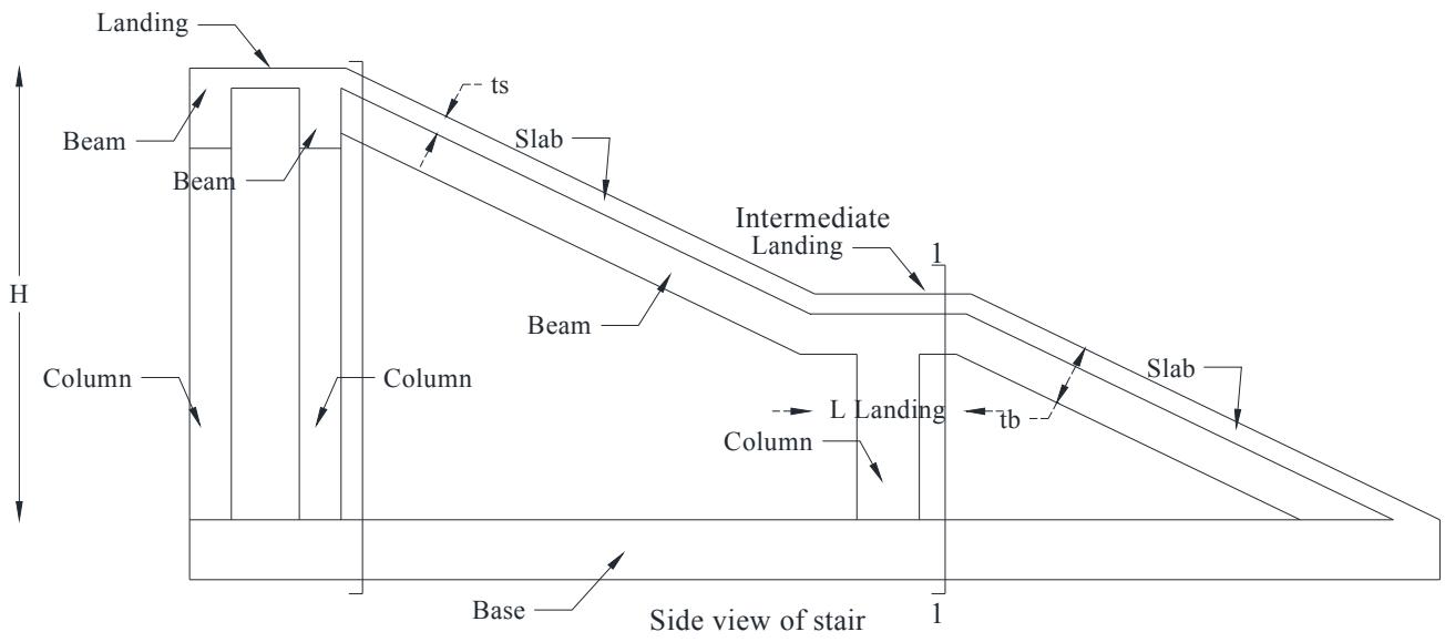
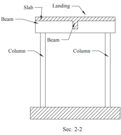
Our lives include this type of staircase as shown in Fig. 1, and its details are shown in Fig. 2
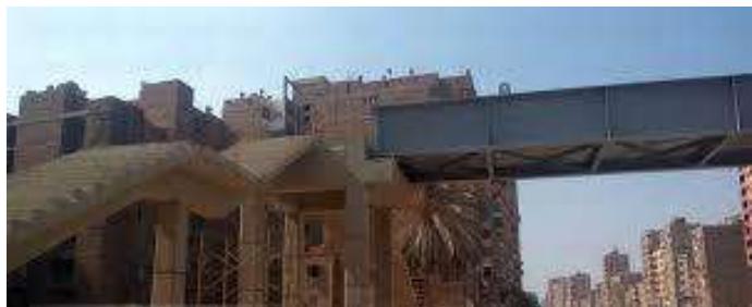
Fig. 1: Photo of Stair
(a)
(b)

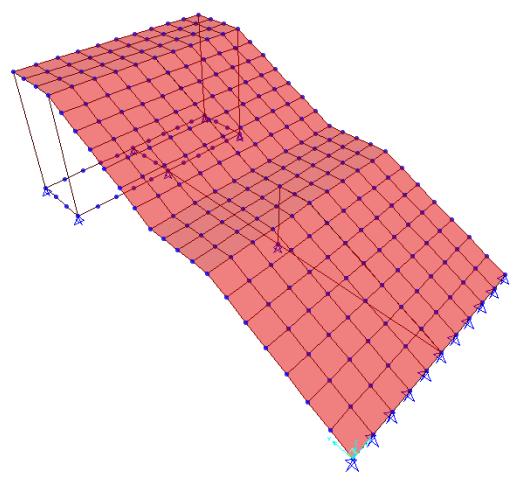
(c) Fig. 2: Details of Staircase: (A) Side View of Stair, (B) Sections of Stair (C) the Model
Numerical techniques such as the finite element method (FEM) may be used to represent objects, such as stairs, as groups of elements or meshes. A final solution is found by combining the results of each element separately. A displacement function is assumed to describe displacements within the elements of the stair, rather than an infinite series. Fig. 2(c) shows the 3D model with finite element analysis of the central beam of the stair; the cross-section of the model can be seen in Fig. 2(b). A finite element analysis was performed using SAP software. Fig. 2(a) shows the model's layout, and Fig. 2(c) shows the stair's eight-node solid elements. This staircase has hinged support at its boundary conditions, as can be seen in Figure 2(c)
Design of the slab according to ACI 318-14. Assumptions for the design are as follows: live load is 0.480 t/m , reinforced concrete density is 2.5 t/m , prismatic compressive strength is 2800 t/m , and yield strength is 42000 t/m . The stair dimensions are 1.50 m landing length, 3 m to 5 m stair height, and 2.0 m to 5.0 m stair width. The results of the design are shown in Fig. 3.
{"image_source":{"path":"images/0d0ddc887c23cc3cc348d09b019d49ca63f90ed8aeaac0858216cc2e670adcaa.jpg"},"content":"","chart_caption":[{"type":"text","content":"Fig. 3: The Relationship Between Stair Width, Slab Thickness, and the Reinforcement"}],"chart_footnote":[]}
Beam design according to ACI 318-14. There are four types of loading investigated, such as live loads on one side of the slab, live loads on both sides of the slab, time histories of earthquakes, and pedestrian dynamic loads. For determining maximum internal forces within the supporting beam, Figure 4 shows the times history analysis of three earthquakes (Sierra Madre, Loma Prieta, and Northridge-01). Axis X represents time and axis Y represents acceleration.
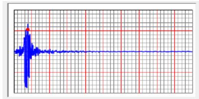
(a) Sierra Madre
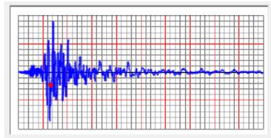
(b) Loma Prieta
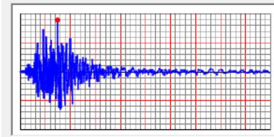
(c) Northridge-01 Fig. 4: Time History of Earthquakes
Details of earthquakes:
-
Earthquake Name: Sierra Madre, Station Name: Altadena - Eaton Canyon, Record Sequence Number: 1641, the magnitude is 5.6 occurred on June 28, 1991, at 7:43 PM.
-
Earthquake Name: Loma Prieta, Station Name: Hollister - South & Pine, Record Sequence Number: 776, the magnitude is 6.93 occurred on October 17, 1989, at 5:04 PM.
-
Earthquake Name: Northridge-01, Station Name: LA - Century City CC North, Record Sequence Number: 988, the magnitude is 6.69 occurred on January 17, 1994, at 4:31 AM.
Walking across the span of a stairway causes vibrations to occur. As a first step, we calculate the vertical pulsating force (F) and the distributed load (W) using equations 1 & 2 from Euro code 2003, and then apply these calculations to our model to calculate the dynamics.
According to the stair data, N for walking and crowds, while N for jogging. This type of stair belongs to the class C (Urban routes subject to significant variation in daily usage). Group size for walking (N=8), for jogging (N=2), Crowd density (person/m ). For walking and jogging cases, the coefficient is 0.8 when L=9.71 m, 0.562 when L=11.94 m and 0.489 when L=14.18 m, whereas for crowd case is 0.114. Tables (1) and (2) show the pulsating forces for walking and jogging, respectively, while Table (3) shows the pulsating distributed loads for crowds
Table 1: Vertical Pulsating Force for Walking Condition
| b | L = 9.71 m, h = 3 m | L = 11.94 m, h = 4 m | L = 14.18 m, h = 5 m | ||||||
| $f_{\text{Hz}}$ | K( $f_{\text{Hz}}$ ) | Amplitude N | $f_{\text{Hz}}$ | K( $f_{\text{Hz}}$ ) | Amplitude N | $f_{\text{Hz}}$ | K( $f_{\text{Hz}}$ ) | Amplitude N | |
| 2 m | 17.946 | 0.02 | 14.387 | 11.577 | 0.02 | 12.438 | 8.094 | 0.020 | 11.778 |
| 2.5 m | 17.084 | 11.2 | 7.924 | 0.024 | 14.028 | ||||
| 3 m | 16.333 | 10.881 | 7.797 | 0.030 | 17.747 | ||||
| 3.5 m | 15.709 | 10.632 | 7.715 | 0.034 | 20.174 | ||||
| 4 m | 15.179 | 10.436 | 7.668 | 0.037 | 21.56 | ||||
| 4.5 m | 14.695 | 10.262 | 7.637 | 0.038 | 22.47 | ||||
| 5 m | 14.276 | 10.078 | 7.596 | 0.040 | 23.68 | ||||
Table 2: Vertical Pulsating Force for Jogging Condition
| b | L = 9.71 m, h = 3 m | L = 11.94 m, h = 4 m | L = 14.18 m, h = 5 m | ||||||
| $f_{\text{Hz}}$ | K( $f_{\text{Hz}}$ ) | Amplitude N | $f_{\text{Hz}}$ | K( $f_{\text{Hz}}$ ) | Amplitude N | $f_{\text{Hz}}$ | K( $f_{\text{Hz}}$ ) | Amplitude N | |
| 2 m | 17.946 | 0.02 | 24.4179 | 11.577 | 0.02 | 22.746 | 8.094 | 0.02 | 22.21 |
| 2.5 m | 17.084 | 11.2 | 7.924 | ||||||
| 3 m | 16.333 | 10.881 | 7.797 | ||||||
| 3.5 m | 15.709 | 10.632 | 7.715 | ||||||
| 4 m | 15.179 | 10.436 | 7.668 | ||||||
| 4.5 m | 14.695 | 10.262 | 7.637 | ||||||
| 5 m | 14.276 | 10.078 | 7.596 | ||||||
Table 3: Vertical Pulsating Distributed Load for Crowd Condition
| b | L = 9.71 m, h = 3 m | L = 11.94 m, h = 4 m | L = 14.18 m, h = 5 m | ||||||||||||
| Hz | K() | Area (m2) | N | Amplitude (N/m2) | Hz | K() | Area (m2) | N | Amplitude (N/m2) | Hz | K() | Area (m2) | N | Amplitude (N/m2) | |
| 2 m | 17.946 | 0.02 | 19.4 | 16 | 1.107 | 11.577 | 0.02 | 23.9 | 20 | 1.007 | 8.094 | 0.020 | 28.4 | 23 | 0.909 |
| 2.5 m | 17.084 | 24.3 | 20 | 0.990 | 11.2 | 29.9 | 24 | 0.882 | 7.924 | 0.024 | 35.5 | 29 | 0.973 | ||
| 3 m | 16.333 | 29.1 | 24 | 0.904 | 10.881 | 35.8 | 29 | 0.808 | 7.797 | 0.030 | 42.6 | 35 | 1.127 | ||
| 3.5 m | 15.709 | 34 | 28 | 0.837 | 10.632 | 41.8 | 34 | 0.750 | 7.715 | 0.034 | 49.6 | 40 | 1.173 | ||
| 4 m | 15.179 | 38.8 | 32 | 0.783 | 10.436 | 47.8 | 39 | 0.703 | 7.668 | 0.037 | 56.7 | 46 | 1.177 | ||
| 4.5 m | 14.695 | 43.7 | 35 | 0.728 | 10.262 | 53.7 | 43 | 0.656 | 7.637 | 0.038 | 63.8 | 52 | 1.161 | ||
| 5 m | 14.276 | 48.6 | 39 | 0.692 | 10.078 | 59.7 | 48 | 0.624 | 7.596 | 0.040 | 70.9 | 57 | 1.151 | ||
The frequency values in Tables 1, 2, and 3 decreased by an average of 3.74%, 2.28%, and 1.05%, respectively, at 3, 4 and 5m of stair height, corresponding to an increase of stair breadth of 25% of the original value. In addition, the frequency values decrease by an average of 32.79%, 31.85%, 30.86%,
29.88%, 28.89%, 27.87% and 27.02%, corresponding to an increase of stair height by 33.3% of the original value, at 2, 2.5, 3, 3.5, 4, 4.5 and 5m of stair breadth respectively. The values of K ( ) are constant above 8 Hz for walking and 7 Hz for jogging and increase as the frequency value decreases beneath the previous values. There is a direct relationship between amplitude and and K ( ), and amplitude increases as these parameters increase.
{"image_source":{"path":"images/82da2944dce29c49184026a943dc4ce1ba2b5009ede30cf7cf3ad59724722247.jpg"},"content":"","chart_caption":[{"type":"text","content":"(a)"}],"chart_footnote":[]} {"image_source":{"path":"images/df83e7d60464f8975fef029977ff85c1f092782e5433862abed8cba07d69cdd9.jpg"},"content":"","chart_caption":[],"chart_footnote":[]}
{"image_source":{"path":"images/28e74224638b86d90bd2c7420bb4db571a76a0d1642851afe9d7de62b13da80a.jpg"},"content":"","chart_caption":[{"type":"text","content":"(b)"},{"type":"text","content":"(c)"},{"type":"text","content":"Fig. 5: Vertical Pulsating Force for (A) Walking Case, (B) Jogging Case and (C) Vertical Pulsating Distributed Load for Crowd Case"}],"chart_footnote":[]} As shown in Figure 5 (a & b), the vertical pulsating force for walking and jogging is distributed with time. For the crowd case, Figure 5c shows the vertical pulsating distributed load distribution with time. The codes have three categories of movement: walking, jogging, and crowds. Walking has a speed of 1.7 m/s, jogging has a speed of 3 m/s, and crowds have a speed of 1.7 m/s. Based on the Euro code, the pedestrian comfort criteria have two conditions: first, the deck's fundamental frequency is greater than 5 Hz for vertical vibrations and 2.5 Hz for lateral and torsional vibrations. Second, the comfort acceleration of any portion of the deck, which should not exceed 0.7 m/s for vertical vibrations, 0.2 m/s for horizontal vibrations resulting from regular use, and 0.4 m/s for exceptional crowding.
III. RESULTS
This study examined five load combinations. First, is the dead load and live load, second is the dead load and live load on one side, third is the dead load and live load with the earthquake, fourth is the dead load and live load on one side with the earthquake, and fifth is the dead load and dynamic load of the pedestrian. Our analysis of the beam involved the use of the critical combination.
{"image_source":{"path":"images/61ae3a8d0cc5587104bed2ef04c8eb172b6d7c9592bd7a25310d862a21e6b8c6.jpg"},"content":"","chart_caption":[{"type":"text","content":"Fig. 6: The Relation Between Fundamental Frequency and Stair Width to Different Stair Height"}],"chart_footnote":[]}
According to Euro code, a comfort criteria verification is necessary if the fundamental frequency of the deck is below 5Hz for vertical vibrations and 2.5Hz for horizontal and torsional vibrations. The fundamental frequencies of the models are over 5Hz as shown in Fig. 6, so no comfort criteria verification is necessary.
b) The Critical Combination of Torsion Moment
Aside from ignoring the first combination of dead load and live load since the torsion moment equals zero, we also ignored the second combination, as it is very small when compared with the other combinations, the torsion moment ranges between 0.1 and 0.45 t.m.
{"image_source":{"path":"images/766ac29725b9e6e8cdec9af631cd02824837684f943548e07f77469dc8d1646a.jpg"},"content":"","chart_caption":[{"type":"text","content":"Fig. 7: The Relation Between Torsion Moment and Breadth of Stair With Various Height"}],"chart_footnote":[]}
- 3rd comb. (H=3m) -- 4th comb. (H=3m) -■ 3rd comb. (H=4m)
A relationship between torsion moment and stair breadth is shown in figure 7, where the breadth ranges from (2m - 5m) and the heights range from (3m - 5m). According to the values, the third and fourth combinations are not significantly different, with the fourth combination being 0.54% to 3.66% larger.
The average torsion moment increases by 7.5% with an increase of 25% from the original breadth for H=3, 19.1% for H=4 and 23.2% for H=5m. Additionally, it is increased by 37.28%, 43.63%, 64.63%, 65.5%, 66.86%, 65.96%, 63.29% for b=2, 2.5, 3, 3.5, 4, 4.5 and 5 m. This corresponds to an increase of 33% from the original height.
c) The critical combination of bending moment
We disregarded the first and second combinations due to small values; values range from 1.3 t.m to 5.7 t.m for these combinations.
{"image_source":{"path":"images/6e49287dc555f8df1cea56eaf10fc581cf469e738401854fd88aac67a90869a2.jpg"},"content":"","chart_caption":[],"chart_footnote":[{"type":"text","content":"◆ 4th comb. (H=4m) ▲ 3rd comb. (H=5m) — 4th comb. (H=5m)"}]}
Fig. 8: The Relation Between Bending Moment and Breadth of Stair With Various Height
Fig. 8 shows that there is no difference between the third and the fourth combination, and based on the values, the third combination is bigger than the fourth combination by ranged values from 0.54% to 1.3%. Based on a 25% increase in stair width, the average increase in bending moments is 2.6%. In addition, bending moments increase with stair height; based on a 33% increase in height, the average increase is 30.5%.
d) The critical combination of shear force
As compared to the other values of the third and fourth combinations, the first and second combinations have small values; ranging from 1.1 to 4.4 t.
According to figure 9, the shear force varies with stair width, which ranges between (2-5m) and different stair heights (3-5m). There is no significant difference between the third and fourth combinations, but the third combination ranges from 1% to 1.6% higher than the fourth. In the case of stair heights 3 and 4 m, shear force increases somewhat, but at 5 m, the shear force increases 13.2% based on a 25% increase over the original breadth. Moreover, it increases proportionally with the - 3rd comb. (H=3m) - 4th comb. (H=3m) - 3rd comb. (H=4m)
- 4th comb. (H=4m) - 3rd comb. (H=5m) - 4th comb. (H=5m)
height of the stairs, with an average increase of 20.72%, 25.13%, 27.57%, 31.64%, 30%, 33.1% and 36.1%, based on an original height increase of 33%.
{"image_source":{"path":"images/d43ca071ed960e6f107ba4980d6662a98b9dc24342a8edc175bf88f62ddf3df3.jpg"},"content":"","chart_caption":[{"type":"text","content":"Fig. 9: The Relation Between Shear Force and Breadth of Stair With Various Height"}],"chart_footnote":[]}
The following equations (Eqs. 3-11) in table (4) show the regression equations for determining the internal forces of beams of varying heights and breadths
Table 4: Regression Equations for Internal Forces of the Beam
| H | Internal force | R2 | |
| 3m | $Mt = -1.2716x^{6} + 27.549x^{5} - 244.54x^{4} + 1136.5x^{3} - 2911.3x^{2} + 3889.6x - 2110.7$ | 1 | Eq. 3 |
| $BM = -1.1277x^{6} + 23.548x^{5} - 201.58x^{4} + 904.86x^{3} - 2244.9x^{2} + 2919.1x - 1509.1$ | 1 | Eq. 4 | |
| $V = 0.8903x^{6} - 18.975x^{5} + 165.64x^{4} - 757.01x^{3} + 1908.1x^{2} - 2511.1x + 1363$ | 1 | Eq. 5 | |
| 4m | $Mt = 1.9333x^{5} - 33.244x^{4} + 222.64x^{3} - 724.47x^{2} + 1147.8x - 704.32$ | 1 | Eq. 6 |
| $BM = 1.0251x^{6} - 20.15x^{5} + 161.56x^{4} - 675.71x^{3} + 1553.5x^{2} - 1856.6x + 962.86$ | 1 | Eq. 7 | |
| $V = 0.8015x^{6} - 15.755x^{5} + 126.3x^{4} - 528.32x^{3} + 121.6x^{2} - 1458.4x + 732.95$ | 1 | Eq. 8 | |
| 5m | $Mt = -1.3218x^{6} + 28.076x^{5} - 243.64x^{4} + 1100x^{3} - 2710.6x^{2} + 3456.9x - 1778.5$ | 1 | Eq. 9 |
| $BM = -0.2976x^{5} + 11.379x^{4} - 117.77x^{3} + 514.13x^{2} - 1002.8x + 813.34$ | 1 | Eq. 10 | |
| $V = -4.8352x^{6} + 99.789x^{5} - 840.77x^{4} + 3700.3x^{3} - 8968.5x^{2} + 11355x - 5842$ | 1 | Eq. 11 |
IV. CONCLUSIONS
The stairs are one of our lives' special structures; perhaps because they carry a heavy live load, or made from a variety of materials, or have different shapes inside and outside of the house.
This search focused on a straight stair with a landing that has one beam in the middle. On the beam, five types of loads are applied: a dead load, a live load applied on one side, a live load applied on both sides, a dynamic load applied for three earthquakes, and a pedestrian load. Analyzing the five combinations of loads led to these conclusions:
1- The maximum torsion moment occurs when a dynamic load is combined with a live load on one side. For maximum shear and bending moments, a dynamic load combined with a live load on both sides is critical.
2- The vibration value of a staircase decreases, as it gets taller and wider.
3- Average torsion moments increase 7.5%, 19.1%, and 23.2% for h=3, 4 and 5m, respectively, corresponding to increased breadths of 25%.
4- According to a 33% height increase, the average torsion moment is 37.28%, 43.63%, 64.63%, 65.5%, 66.86%, 65.96% and 63.29% for b=2, 2.5, 3, 3.5, 4, 4.5, 5 m.
5- For a 25% increase in breadth, the average increase in bending moment is 2.6% for all heights, and for a 33% increase in height, the average increase is 30.5% for all breadths.
6- A 25% increase in breadth results in an average increase of 5.5% in shear force for H = 3 m and H = 4 m, and 13.2% for H = 5 m.
7- Based on an increase of 33% from the original height, the average shear force increase for b = 2, 2.5, 3, 3.5, 4, 4.5 and 5 m is 20.72%, 25.13%, 27.57%, 31.64%, 30%, 33.1% and 36.1%.
8- The equations in table (1) enable the designer engineer to calculate the internal forces of the supporting beam.
ACKNOWLEDGEMENTS
I would wish to state my gratitude to ALLAH for giving me the will to accomplish this work. My special thanks and admiration go to Professor Dr Sherif Ahmed Mourad, Professor of Steel Structures and Bridges of the Civil Engineering Department, Faculty of Engineering, Cairo University, Egypt, for his outstanding and sincere assist and valuable advice during the period of this study.
hlmData availability
Some or all data, models, or code that support the findings of this study are available from the corresponding author upon reasonable request.
Declaration of Interest Statement
We have no conflicts of interest to disclose.
Notation
F The vertical pulsating force. N
The reference amplitude of the applied fluctuating force. N
A combined factor to deal with (a) the effects of a more realistic pedestrian population, (b) harmonic responses and (c) relative weighting of pedestrian sensitivity to response.
γ A reduction factor to allow for the unsynchronized combination of actions in a pedestrian group, a function of damping and effective span.
N The number of pedestrians in the group.
The natural frequency of the vertical mode under consideration. Hz t Elapsed time. Sec.
w Vertical pulsating distributed load
ρ Crowd density persons/m2
S The span of the bridge m b The width of the bridge subject to pedestrian loading m
A factor that reduces the effective number of pedestrians when loading from only part of the span contributes to the mode of interest. .
Conflict of Interest
The authors declare no conflict of interest.
Ethical Approval
Not applicable
Data Availability
The datasets used in this study are openly available at [repository link] and the source code is available on GitHub at [GitHub link].
Funding
This work did not receive any external funding.
References
Cite this article
Related Research



Special Issue
Launch a focused special issue to highlight research, emerging trends, and expert insights in your academic field.
