


IntelliPaper
Abstract
The rate at which energy is lost by human activities is enormous. There is need to work on how to generate more energy and minimize the usage of the generated energy. In an internal combustion engine, there is need to focus on gaining energy usage by using generated heat during combustion process. To reduce the energy usage, emission rate and improve the efficiency of four-stroke internal combustion spark ignition engine, the four-stroke internal combustion spark ignition engine is modified into a six-stroke internal combustion spark ignition engine. The heat generated from four-stroke cycle is used in six-stroke cycle for additional power stroke and exhaust stroke of the piston in the same cylinder. There is an injection of water which form steam with the help of generated heat from four-stroke cycle which forces down the piston for additional power stroke and the piston comes up to expel the exhaust gases out of the cylinder. With the injection of water into the cylinder, there is no need of cooling system as in four-stroke Otto cycle which makes the engine become lighter and 25% fuel and power efficiency over the normal Otto cycle.
Explore Digital Article Text
I. INTRODUCTION
The six-stroke internal combustion spark ignition engine principle is based on the conventional four-stroke internal combustion spark ignition engine but with additional features for energy saving (fuel consumption), maximum power optimization, and cooling rate e.t.c. The additional features include the addition of other two strokes in which the engine uses the waste heat from the four-stroke internal combustion spark ignition engine (Otto cycle or Diesel cycle) for additional power stroke and exhaust stroke of the piston in the cylinder. The design uses steam as working fluid for the additional power stroke.
1.1 Background of the Study
In an internal combustion engine, most of the fuels energy is lost as heat and as pollutant. The heat is aired out by the radiator. There is need to concentrate on the rate of energy loss as the world is working on how to generate more energy and minimize the usage of already generated energy. The consequence of energy cannot be overemphasized in the view of human technology; every aspect of human endeavor requires a consistent and viable source of energy and how to maintain it. There is need to focus on gaining of energy by the usage of this heat generated in the internal combustion engine. The six-stroke engine was developed since the 1990s, describes two different approaches in the internal combustion engine, to improve its efficiency and reduce emissions. The engine entrances the waste heat from the four-stroke of an internal combustion engine being Otto cycle or Diesel cycle and uses it to get an additional power and exhaust stroke of the piston in the same cylinder. Designs either use steam or air as the working fluid for the additional power stroke. The additional stroke cools the engine and removes the need for a cooling system making the engine lighter and giving 40% increased efficiency over the normal Otto cycle or
Diesel Cycle (Ahmad, 2012). The pistons in this six-stroke engine go up and down six times for each injection of fuel. These six-stroke engines have two power strokes: one by fuel, one by steam or air. The currently notable six-stroke engine designs in this class are the Crower's six-stroke engine, invented by Bruce Crower of the U.S.A; the Bajulaz engine by the Bajulaz S A Company, of Switzerland; and the Velozeta's Six-stroke spark ignition engine built by the College of Engineering, at Trivandrum in India.
The second approach to the six-stroke internal combustion spark ignition engine uses a second opposed piston in each cylinder which moves at half the cyclical rate of the main piston, thus giving six piston movements per cycle. Functionally, the second piston replaces the valve mechanism of a conventional engine and also it increases the compression ratio. The currently notable six-stroke spark ignition engine designs in this class include two designs developed independently: The Beare Head engine, invented by Australian farmer Malcolm Beare, and the German Charge pump, invented by Helmut Kottmann.
1.2 Strokes of Four-Stroke Spark Ignition Engine
The working principle of the four-stroke spark ignition engine:
First Stroke: Here, the inlet valve opens for the air-fuel mixture from the carburetor which is sucked into the cylinder through the inlet manifold.
Second stroke: The second stroke of the internal combustion engine which is the compression stroke, the piston moves from Bottom Dead Centre (BDC) to the Top Dead Centre (TDC) to compress the air-fuel mixture in which both the inlet and outlet valve were closed.
Third stroke: This is the power stroke on an internal combustion engine in which the compressed air-fuel mixture is ignited by the spark plug. The two valves remain closed and the piston is forced down from Top Dead Centre (TDC) to Bottom Dead Centre (BDC).
Fourth stroke: The fourth stroke of an internal combustion engine is the exhaust stroke where the exhaust (outlet) valve opens to allow the exhaust (burned gases) out of the engine cylinder. Here, the piston moves from the Bottom Dead Centre (BDC) to the Top Dead Centre (TDC) and the inlet valve remain closed.
1.3 Strokes of a Six-stroke Spark Ignition Engine
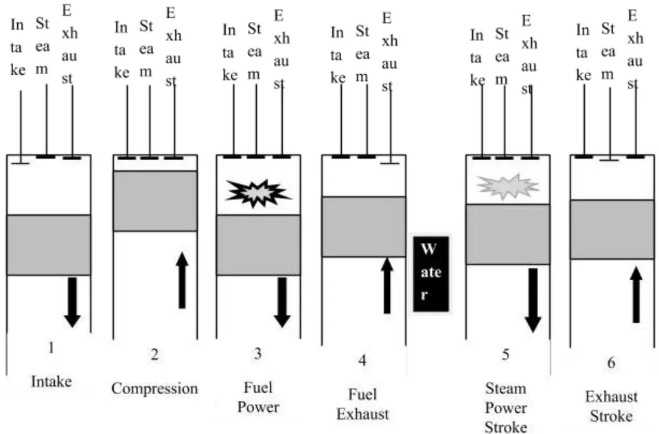
Fifth stroke: In the fifth stroke of an internal combustion engine the piston is force down by the heat generated at the exhaust stroke and the steam formed by the injection of water under pressure and temperature through the water injection nozzles into the cylinder. The piston is forced down from the Top Dead Centre (TDC) to the Bottom Dead Centre (BDC) for the second power stroke.
Sixth stroke: This is the second exhaust cycle where the piston moves from the Bottom Dead Centre (BDC) to the Top Dead Centre (TDC). The exhaust valve opens for the passage of gases out of the cylinder.
II. RESEARCH METHODOLOGY
2.1 Six-Stroke Engine
This Design uses steam as a working fluid for the additional power stroke as well as extracting power; the additional stroke cools the engine and removes the cooling system of the engine making the engine lighter and increased efficiency over the Otto cycle.
2.2 Additional Strokes Introduce
Fifth stroke: At the fifth stroke which is the first additional stroke out of the two strokes added to the four-stroke of an internal combustion engine, the heat evolved at the exhaust of the forth cycle were use directly. There is intake of water by water injection into the super-heated cylinder, the water explodes into steam then forces the piston down for the second power stroke. This also cools the engine. The water injection consist of three main components; injector, water pressurizing system and electronic control system.
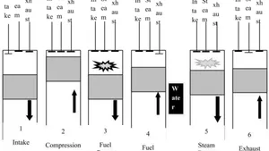
Sixth stroke: All the vapors at the top of the piston inside the cylinder and gases are thrown out from the combustion chamber through the exhaust valve and water vapor can be collected by a condenser which is attached to the exhaust port so that the water can be reused. The processes are explained in the figure 2.1 below:
2.3 Engine Modification of Four-Stroke Spark Ignition Engine
The conventional four-stroke engine was modified by working on some specific part for the addition of two more strokes for additional power to the four-stroke engine. These modifications are:
2.3.1 Camshaft/Crankshaft sprocket
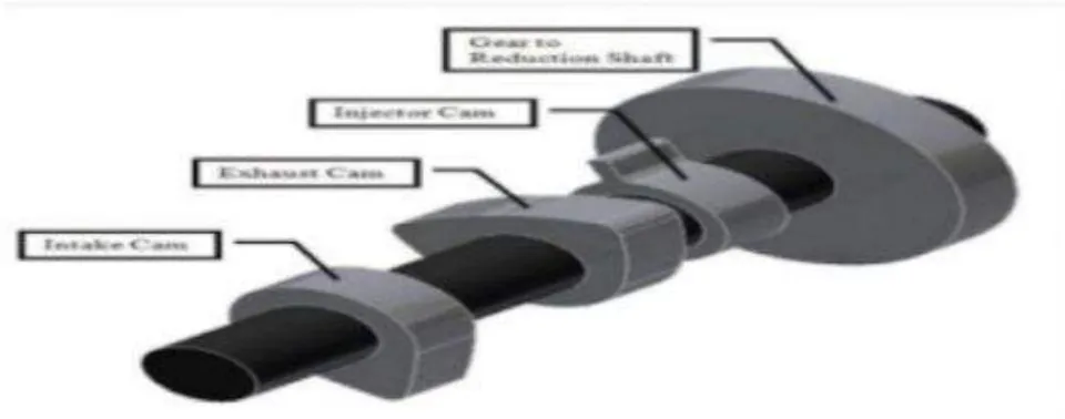
Camshaft is a rod or shaft to which cams are attached. Cams are non-circular wheels, which operate the cylinder valves of an internal combustion engine and are also used to operate other gear-driven engine components. Camshaft design can determine whether the camshaft can help the engine to produce heavy torque. The cams on the camshaft operate the intake and exhaust valves of the engine. The original angular speed of the camshaft is one-half that of the crankshaft, such that the camshaft rotates once for every two revolutions (four-stroke) of the crankshaft. The six-stroke camshaft has been designed to turn one revolution every three revolutions (six-stroke) of the crankshaft.
In an internal combustion engine, camshaft is a cylindrical rod running at the length of the cylinder bank with a number of a long lobes protruding from it, one for each valve. The cam lobes force the valve open by pressing on the valve as they rotate. The main function of camshaft is to operate poppet valve
In 2-stroke engine,
If there is two stroke of the piston and one revolution (360°) of the camshaft, the revolution of the crankshaft of the two stroke of the piston in degree will be:
For 2 -stroke, power stroke occurs once in every revolution of crankshaft For 4-stroke engine,
If firing takes place once after every 4-stroke
For 6 - stroke engine,
If power will occur once in every
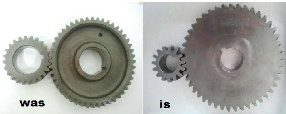
Therefore the corresponding sprocket of four strokes to six-stroke having teeth ratio :
This gives ratio 1:3
This makes it necessary to keep the camshaft pulley three times bigger than crank shaft pulley for the 6- stroke engine.
2.3.2 Camshaft Modification
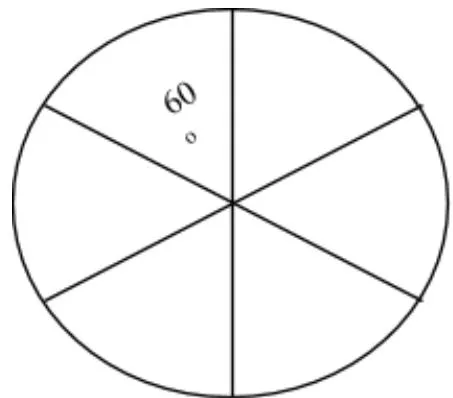
In a six stroke internal combustion engine, the cam was divided into six, the exhaust has two (2) lobes, one to open the exhaust valve at the forth stroke and at the sixth stroke to push out the steam.
2.3.3 Timing Gear
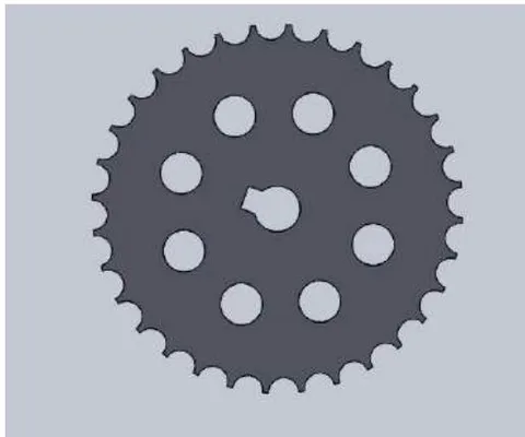
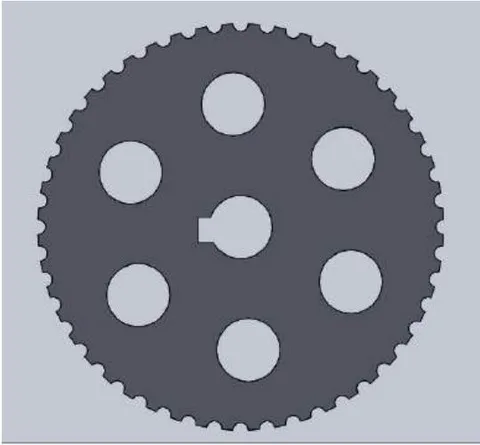
The gear train (sprocket) with two to one reduction through which the crankshaft drives the camshaft and controls valve timing in an internal combustion spark ignition engine. The timing gear of a four-stroke internal combustion spark ignition engine consists of 32 teeth with a cam revolution ratio of 1:2.
If for every two rotations of a crank, the timing gear rotates a single rotation. The timing gear of a six-stroke internal combustion spark ignition engine will consists of
.48 teeth with a cam revolution ratio of 1:3. Here for every three rotations of a crank the timing gear rotates a single rotation.
2.3.4 Cam Profile Design
2.3.5 The design of the cam profile is very vital and it will be design on the basis of the following
The distance that the valve will move toward the piston
The time for the valve to remain open for exhaust gases
The time it will take for the closing of the valve which is the same as that of opening time
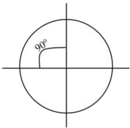
The four-stroke camshaft profile: the four-stroke camshaft has a of design in angle; the circle was divided into four.
The camshaft has two lobes, one for intake valve and one for exhaust valve
2.3.5.1 Six-stroke Camshaft Profile
The six-stroke camshaft profile has a design of an angle; the circle was divided into six. The camshaft has four lobes, two for the intakes valve (for the intake of air-fuel mixture), two to allow injection of water at the fifth stroke and two for the exhaust valve (for the first exhaust after the combustion and for the second exhaust of the steam after the fifth stroke)
2.4 Fuel Tank
The fuel tank of four-stroke internal combustion spark ignition engine has to be divided into two for the six-stroke internal combustion spark ignition engine as one side is for fuel and the other will be for water and the water has to be distill and pure.
2.5 Cam Follower Modification
The four-stroke internal combustion spark ignition engine has its bottom shape follower in flat pattern. For the six-stroke internal combustion spark ignition engine, the follower has to be in roller or spherical shape has its contact area is lesser.
2.6 Injection of Water System
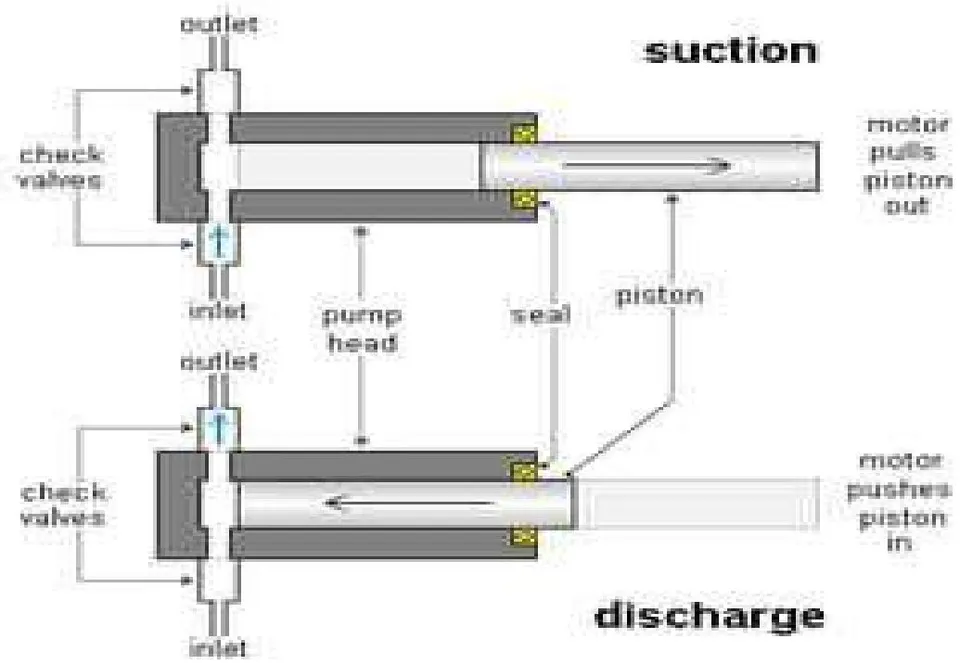
The injection of the water system is done with the help of a water injector operated by the cam. This can be achieved with the use of a water metering pump. The water metering pump is a positive displacement pump capable of driving a fixed quantity of water into the cylinder at regular intervals independent of the back pressure applied.
2.7 Analysis of Internal Combustion Spark Ignition Engine
2.7.1 Indicated Power
The indicated power can be defined as the power remaining to drive the piston after some are loss to the coolant, radiation and exhaust For four-stroke engine n: the indicated power is thus.
Where:
ip = indicated power (kW)
= indicated mean effective pressure n = is the number of power stroke
and speed of the engine (r.p.m)
L = length of the stroke (m)
A = cross - sectional area of the piston ( ) For four-stroke engine, since N = N/2
Therefore substitute for the value of n
(2.3) For six-stroke engine n: the indicated power is as follows:
Where
2.7.2 Percentage Difference in Indicated Power
The percentage difference in the indicated power of four-stroke internal combustion spark ignition engine and the six-stroke internal combustion spark ignition engine may be calculated as:
From equation (3.3) and equation (3.5)
2.7.3 Break Power
Is the useful power trans mitted by the piston to the crankshaft
Where BP = Break Power
Assuming the Torque to be 58Nm, N to be 900 r.p.m For four-stroke internal combustion spark ignition engine
For six-stroke internal combustion spark ignition engine where
2.7.4 Percentage Difference in Break Power
The percentage difference in the break power of four-stroke internal combustion spark ignition engine and the six-stroke internal combustion spark ignition engine may be calculated as:
From the result of equation 3.7 and equation 3.8, the percentage difference can be calculated as:
2.7.5 Mechanical Efficiency
The mechanical efficiency can be defined as the ratio of the brake thermal efficiency to indicated thermal efficiency.
2.7.6 Thermal Efficiency
The thermal efficiency can be defined as the ratio of the power produced to the energy in the fuel burned to produce this power. It can be expressed as follows:
Where fuel mass flow rate
Where P can be either break power or indicated power, therefore
Fuel Consumption
Let
take Torque to be 58Nm
In four-stroke internal combustion spark ignition engine there is only one useful power stroke and other three strokes idle, the percentage useful power stroke may be calculated as
Where number of useful power stroke = 2
While:
In six-stroke internal combustion spark ignition engine, there is two useful power stroke and four stroke being idle, the percentage useful may be calculated as% useful power stroke = Where number of useful power stroke = 2 Number of stroke = 6
2.8.1 Percentage Difference of Useful Power Stroke
The percentage difference of the useful power stroke of four-stroke internal combustion spark ignition engine and the six-stroke internal combustion spark ignition engine may be calculated as:
From the result of equation 3.7 and equation 3.8, the percentage difference can be calculated as:
2.9 Piston Movement of Six-Stroke Engine
For six-stroke engine, the movement of the piston continues at the fourth stage of the four-stroke
(2.15) engine. The piston moves from the Top Dead Centre to Bottom Dead Centre for another expansion which occurs between the top and Bottom Dead Centre at of the camshaft crankshaft.
The last movement of the piston for six-stroke engine is from Bottom Dead Centre to Top Dead Centre for the second exhaust of gas at of the camshaft crankshaft.
{"image_source":{"path":"images/34be080fbc85397a210efad29ae7381e39216c16239a8991ab7615caf43a39dc.jpg"},"content":"","chart_caption":[{"type":"text","content":"Figure 2.8: Angle of crankshaft of Six- Stroke Engine"},{"type":"text","content":"Design of Six-Stroke Internal Combustion Spark Ignition Engine"}],"chart_footnote":[]}
III. RESULTS
3.1 Thermal Efficiency
The thermal efficiency can be defined as the ratio of the power produced to the energy in the fuel burned to produce this power. Using equation (2.13) and (2.14) the result of break thermal efficiency for four-stroke engine and six-stroke engine are shown in the table 3.1 and 3.2
Table 3.1: Result of Raw Data for Break Thermal Efficiency of Four-Stroke Engine Calculation
| S/No | Assumption | 1 | 2 | 3 | 4 | 5 |
| 1 | Load W (kg) | 0 | 0 | 0 | 0 | 0 |
| 2 | Speed N (r.p.m.) | 900 | 1200 | 1500 | 1800 | 2000 |
| 3 | Volume of fuel ( ) | 0.00001 | 0.00001 | 0.00001 | 0.00001 | 0.00001 |
| 4 | Fuel consumption time (sec) | 42 | 34 | 30 | 26 | 24 |
| N for 4 stroke | 0.5 | 0.5 | 0.5 | 0.5 | 0.5 | |
| Torque = 58Nm | 58 | 58 | 58 | 58 | 58 | |
| caloric value of fuel = 46400kJ/kg | 46400 | 46400 | 46400 | 46400 | 46400 | |
| Density of fuel | 737 | 737 | 737 | 737 | 737 | |
| Break Power | 2.73354 | 3.64472 | 4.5559 | 5.46708 | 6.074533 | |
| fuel mass flow rate | 0.000175 | 0.000217 | 0.000246 | 0.000283 | 0.000307 | |
| Break Thermal Efficiency% | 33.57293 | 36.23745 | 39.96777 | 41.56649 | 42.63229 |
Table 3.2: Result of Raw Data for Break Thermal Efficiency of Six-Stroke Engine Calculation
| S/No | Assumption | 1 | 2 | 3 | 4 | 5 |
| 1 | Load W (kg) | 0 | 0 | 0 | 0 | 0 |
| 2 | Speed N (r.p.m) | 900 | 1200 | 1500 | 1800 | 2000 |
| 3 | Volume of fuel ( ) | 0.00001 | 0.00001 | 0.00001 | 0.00001 | 0.00001 |
| 4 | Fuel consumption time (sec) | 42 | 34 | 30 | 26 | 24 |
| N for 6 stroke | 0.666667 | 0.666667 | 0.666667 | 0.666667 | 0.666667 | |
| Torque = 58Nm | 58 | 58 | 58 | 58 | 58 | |
| caloric value of fuel = 46400kJ/kg | 46400 | 46400 | 46400 | 46400 | 46400 | |
| Density of fuel | 737 | 737 | 737 | 737 | 737 | |
| Break Power | 3.64472 | 4.859627 | 6.074533 | 7.28944 | 8.099378 | |
| fuel mass flow rate | 0.000175 | 0.000217 | 0.000246 | 0.000283 | 0.000307 | |
| Break Thermal Efficiency% | 44.76391 | 48.3166 | 53.29037 | 55.42198 | 56.84306 |
| Brake Thermal Efficiency | ||
| Speed N (r.p.m) | 4-stroke% | 6-stroke% |
| 900 | 33.57 | 44.76 |
| 1200 | 36.24 | 48.32 |
| 1500 | 39.97 | 53.29 |
| 1800 | 41.57 | 55.42 |
| 2000 | 42.63 | 56.84 |
{"image_source":{"path":"images/dde6c264b3d96275ce1d9b229827e2f5147b3bf7ec7070b56a4ea0d6162db6c0.jpg"},"content":"","chart_caption":[{"type":"text","content":"Figure 3.1: Efficiency (%) of Four-Stroke and Six-Stroke Engine"}],"chart_footnote":[]}
3.2 Pressure - Volume of Six-Stroke Engine
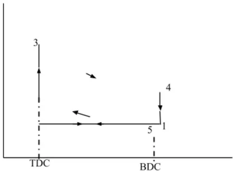
The constant volume cycle (Otto cycle) volume of six-stroke internal combustion spark ignition engine continue from the fourth stage of the normal convention of the four-stroke internal combustion spark ignition engine. The resulting pressure -volume diagram for the six-stroke internal combustion spark ignition engine is shown in figure 3.2.
3.3 Percentage Differences in Power
The output power percentage differences of four-stroke internal combustion spark ignition engine and the six-stroke internal combustion spark ignition engine using equation are shown in table 3.4 below:
Table 3.4: Six-Stroke and Four-Stroke Output Percentage Differences
| S/NO | Power | Percentage Differences (%) |
| 1 | Indicated Power | 25% |
| 2 | Break Power | 25% |
| 3 | Useful Power Stroke | 25% |
3.4 Discussion of Analysis of Internal Combustion Spark Ignition Engine
From equations (2.3) and (2.5), it shows that some of the power produced in the cylinder to drive the piston after combustion are loss to radiation and exhaust of the six-stroke internal combustion spark ignition engine is more than that of four-stroke internal combustion spark ignition engine as the six-stroke requires no cooling system. Also the results from equations (2.8) and (2.9) implies that the power transmitted from the piston to drive the crankshaft is greater than that of four-stroke internal combustion spark ignition engine which gives the six-stroke internal combustion spark ignition engine a greater output (speed) with the same energy (fuel) burned resulting in reduction of fuel burned with the same distance covered of about 25%.
Table 3.4 shows that the six-stroke internal combustion spark ignition engine is of 25% power efficiency than that of four-stroke internal combustion spark ignition engine.
IV. CONCLUSION AND RECOMMENDATION 4.1 Conclusion
The introduction of six-stroke internal combustion spark ignition engine has positive impact in the world economy as it reduces the rate of energy consumption, and reduces the rate of polluting the environment with exhaust flame. The temperature of the engine is lower due to the injection of water which improved the cooling system and increases its overall efficiency. With all the desired qualities and modification, the six-stroke internal combustion spark ignition engine is better than the four-stroke internal combustion spark ignition engine.
4.2 Recommendation
This project design should be recommended for further research base on the material properties that is of thermal resistant alloys as the components will be subjected to thermal stresses that will be developed due to water injection into the superheated cylinder in which the rapid temperature changes can cause fracture or micro cracking at low cost.
WEBSITES
http://www.bajulazsa.com/site/sixstrokeexp lanations.html http://www.velozetas.com/site/sixstrokeexplanat ions;html
Conflict of Interest
The authors declare no conflict of interest.
Ethical Approval
Not applicable
Data Availability
The datasets used in this study are openly available at [repository link] and the source code is available on GitHub at [GitHub link].
Funding
This work did not receive any external funding.
References
Cite this article
Related Research


Special Issue
Launch a focused special issue to highlight research, emerging trends, and expert insights in your academic field.