





IntelliPaper
Abstract
This research paper presents a theoretical investigation into the optimization of texture position in two-lobe journal bearings using finite element method (FEM). Journal bearings play a vital role in various industrial applications by supporting rotating machinery and ensuring efficient operation. Surface texturing has emerged as a promising technique to enhance tribological performance by altering the hydrodynamic lubrication mechanisms. The present study is focussed on the influence of texture position on dynamic stability and operational efficiency. Through the development of a comprehensive FEM model, the dynamic behavior of the bearing system is analyzed under varying texture positions. The effects of different texture locations on the dynamic coefficients, including stiffness and damping, are evaluated to understand their impact on stability and performance. Subsequently, the operational performance metrics, such as friction reduction and load-carrying capacity, are quantified. The optimization process involves systematic exploration of texture positions using numerical algorithms to identify the optimal configuration that maximizes dynamic stability and operational efficiency. The outcomes of this study provide insights into the intricate interplay between texture placement and the bearing's dynamic response, shedding light on the underlying mechanisms that lead to improved performance.
Explore Digital Article Text
I. INTRODUCTION
Two-lobe journal bearings find extensive use in various industries due to their capacity for high-speed, high-load support with minimal friction and wear. However, surface texture significantly impacts their performance. By enhancing lubrication and decreasing friction and wear, surface texturing improves these bearings. Such textures aid in generating hydrodynamic pressure and maintaining lubricating films. Texture attribute like location influence bearing performance. Optimal design parameters can be identified through numerical simulations and experiments.
Several studies have been undertaken to explore the effect of texture location on the performance parameters of two-lobe journal bearings. Hsu et al. [1] explored texture location's impact on performance of dynamic-loaded two-lobe journal bearings. Their study revealed that placing the texture at the leading edge enhanced load capacity and decreased friction, as opposed to mid-span or trailing edge placement. Kim et al. [2] investigated the impact of texture location and depth on two-lobe journal bearing performance under different conditions. They found that a 10 m deep texture placed at the bearing's trailing edge improved stability and decreased friction. In contrast, placing the texture at the mid-span yielded opposite effects. Lee et al. [3] studied the effect of texture location on the performance of two-lobe journal bearings under various lubrication regimes. They found that placing the texture at the mid-span of the bearing surface improved its load-carrying capacity and reduced its friction coefficient vis-a-vis placing the texture at the edges of the bearing surface.
Park et al. [4] studied the effect of texture location and depth on the performance characteristics of two-lobe journal bearings. They found that placing the texture at the edges of the bearing surface improved its stability and reduced its friction coefficient, while placing the texture at the mid-span of the bearing surface had the opposite effect. Experimental and numerical investigations were undertaken by Karthikeyan et al. [5] to explore the influence of texture location on the load-carrying capacity of two-lobe journal bearings. They found that the load-carrying capacity increased by 7.5% when the texture was located at 60° from the leading edge of the bearing. Using a combined experimental and numerical approach, Li et al. [6] conducted a study to examine the impact of texture location on the friction and wear characteristics of two-lobe journal bearings. Their findings revealed that the lowest friction coefficient and wear rate were achieved when the texture was located at 120° from the leading edge of the bearing.
Wu et al. [7] studied the effect of texture location on the stability of two-lobe journal bearings using a nonlinear dynamic analysis. They found that the stability threshold increased by 22.5% when the texture was located at from the leading edge of the bearing. Zhang et al. [8] conducted a study to explore the influence of texture orientation and location on the performance characteristics of two-lobe journal bearings. The researchers discovered that placing the texture at the edges of the bearing surface with a orientation resulted in enhanced load-carrying capacity and reduced friction coefficient, in contrast to placing the texture at the mid-span of the bearing surface with a orientation. Zhou et al. [9] conducted an experimental study to explore the effect of different texture locations on the performance characteristics of two-lobe journal bearings. Their results revealed that the texture location had a significant impact on the friction coefficient and the bearing's stability. They concluded that the optimal texture location was at the midpoint of the bearing's length.
Zhang et al. [10] studied the impact of texture location on the performance characteristics of two-lobe journal bearings under misalignment conditions using numerical simulations. They reported that the maximum oil film pressure was obtained when the texture was located at from the leading edge of the bearing. In another study, Qiu et al. [11] conducted numerical simulations to investigate the impact of texture location on the lubrication performance parameters of journal bearings. The authors found that the optimal texture location depended on the load and the sliding velocity. Wang et al. [12] investigated the effect of texture location on the dynamic characteristics of a two-lobe journal bearing. The findings clearly indicated that the placement of textures had a notable impact on the dynamic stiffness and damping characteristics of the bearing. Based on these results, the authors reached the conclusion that by optimizing the location of textures, the dynamic performance of two-lobe journal bearings could be improved.
Li et al. [13] investigated the effect of texture location and texture size on the performance of a two-lobe journal bearing. The results showed that the texture location and size had a significant effect on the friction coefficient and load capacity of the bearing. The authors proposed an optimization method to determine the optimal texture location and size for improved bearing performance. Wang et al. [14] studied the impact of texture location and pattern on the performance parameters of two-lobe journal bearings. The authors found that placing the texture at the edges of the bearing surface with a sinusoidal pattern improved its load-carrying capacity and reduced its friction coefficient vis-a-vis placing the texture at the mid-span of the bearing surface with a rectangular pattern.
Li et al. [15] investigated texture positions' influence on two-lobe journal bearings using both experiments and simulations under varied loads. Their findings indicated the midpoint as the optimal texture location for all loads, impacting oil film thickness, pressure distribution, and friction coefficient of the bearing. Zhao et al. [16] studied the effect of texture location on the load carrying capacity and friction coefficient of a two-lobe journal bearing. The study's findings revealed a substantial influence of texture location on both the load carrying capacity and friction coefficient of the two-lobe journal bearings. Consequently, the authors concluded that by optimizing the location of textures, the performance characteristics of these bearings could be enhanced. Another study by Liu et al. [17] examined the effect of texture location on the stability of a two-lobe journal bearing. The authors found that the texture location had a significant effect on the stability of the bearing.
They proposed an optimization method to determine the optimal texture location for improved bearing stability.
After an extensive review of the available literature, it has become evident that the understanding of the influence of texture location on the performance of two-lobe journal bearings is still insufficient. Consequently, this study aims to investigate the impact of texture location on the dynamic stability and performance parameters of two-lobe journal bearings operating under laminar flow conditions. Fig.1 depicts the schematic diagram of a smooth/textured two-lobe journal bearing for reference.
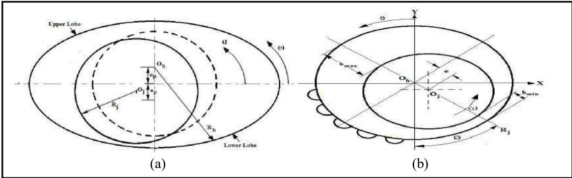 Fig. 1: (a) Depicts the Geometry of Smooth Two-Lobe Journal Bearing, (b) Textured Two-Lobe Journal Bearing
II. ANALYSIS AND MATHEMATICAL MODELING
The non-dimensional form of the governing Reynolds equation for a two-lobe journal bearing, under the assumptions of Newtonian, isoviscous, and laminar fluid flow, can be mathematically represented as per previous studies [18, 19].
Where , and are cross apparent viscosity integrals and can be calculated as
Fluid - Film Thickness ( )
The dimensionless expression for the fluid-film thickness of a two-lobe journal bearing system can be derived as per the findings from previous research [20].
Where and represent the local coordinates of the lobe center for the ith lobe.
The fluid-film thickness (h) for the upper-lobe of the two-lobe bearing system can be expressed as follows:
The fluid-film thickness for the lower-lobe of the two-lobe bearing system can be expressed as follows:
Where dimple depth.
In the case of a bearing surface featuring spherical textures, the dimple depth ( ) can be represented by the following expression, as indicated in earlier investigations [21, 22].
2.1 FEM formulation
The fluid domain is discretized using four-noded quadrilateral iso-parametric elements. The pressure distribution within an element is assumed to be linear and can be mathematically expressed as :
Where represents the shape function of the element and denotes the number of nodes per element. By employing Galerkin's Finite Element Method (FEM) approach, the global system of equations can be expressed in algebraic form as detailed in previous research [21].
Where, & are the direction cosines and i, j = 1, 2......n.
2.2 Boundary Conditions
The solution is obtained by applying the following boundary conditions:
a) The pressure at nodes located on the external boundary is set to zero.
b) The pressure of the fluid at the trailing edge of the positive region is assumed to be zero.
c) The pressure at the leading edge is considered to be atmospheric.
By simultaneously solving Equation (4), the pressure and fluid flow are determined. This approach is employed as, at each node, one of the two variables is already known.
2.3 Performance Characteristics
Static performance characteristics
Load carrying capacity ( ): The fluid-film reaction components along the X and Z directions can be expressed as per the findings from a previous study [23].
The resultant load carrying capacity is expressed as
Attitude angle : The calculation of the attitude angle is performed using the following method:
Fluid-film Frictin force ( ): The computation of the friction force in a journal bearing is accomplished using the equation provided in previous research [24].
The friction force in a journal bearing is determined based on the equation (9), wherein represents the normalized Couette shearing stress. In the case of laminar flow, is set to zero. The coefficient of fluid-film friction can be calculated using the following relation
Dynamic performance characteristics
The dynamic performance characteristics refer to the behavior and performance of a system under varying dynamic conditions. By analyzing the dynamic performance characteristics, researchers can assess and optimize the system's response to dynamic forces and vibrations, ensuring its reliability, efficiency, and safety.
Fluid-Film Stiffness Coefficients: The dimensionless form of the fluid-film stiffness coefficients can be expressed as per the findings presented in previous research .
The index 'i' corresponds to the force direction, while the index 'q' pertains to the displacement direction concerning the coordinates of the journal center. The matrix of fluid-film stiffness coefficients can be represented as follows:
Fluid-film Damping Coefficients: In non-dimesionalized form, the coefficients of fluid-film damping can be represented as .
Where represents the velocity components at the center of the journal. The matrix of fluid-film damping coefficients can be expressed as
III. SOLUTION PROCEDURE
The study employed Finite Element Method (FEM) to analyze the effect of texture location on the performance of two-lobe journal bearings. The authors detailed the selection of axial and circumferential elements and the overall methodology in their published work. To calculate static, dynamic, and stability characteristics, a systematic approach is developed considering texture location. A visual representation of the computation steps is given in Fig. 2, offering a clear and succinct depiction of the process.
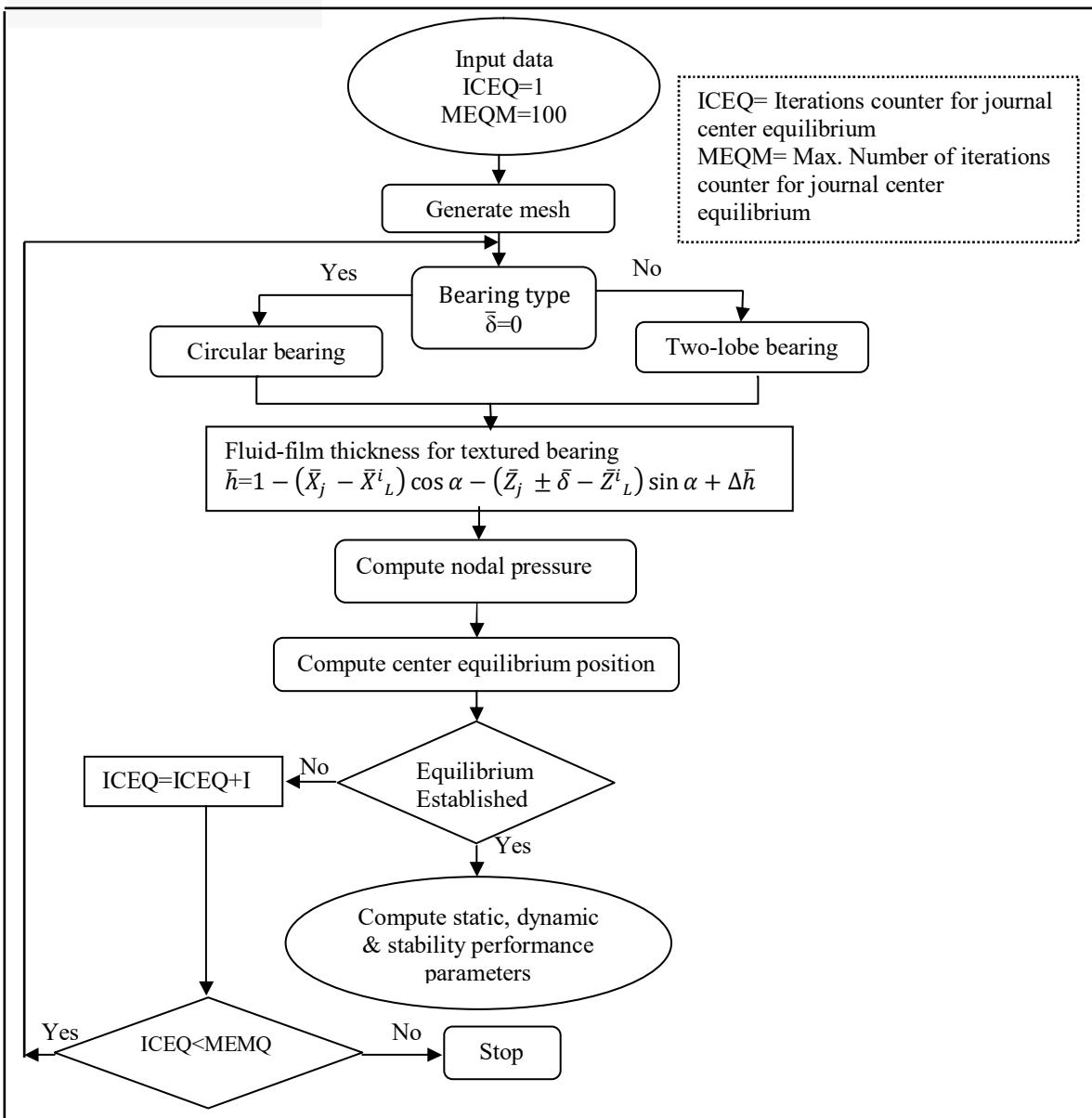 Fig. 2: Flow Chart of Solution Procedure
VI. RESULTS AND DISCUSSIONS
This study explores performance in smooth and textured two-lobe journal bearings through varied texture positions. A MATLAB code is developed and validated against prior research, ensuring computational accuracy. Static parameters align with Sinhasan and Goyal's results, and dynamic parameters match Lund and Thomson's findings, as shown in Tables 1 and 2. The study's operational and geometric parameters, outlined in Table 3, are derived from Singh and Awasthi's work.
Table 1: Comparative Analysis of Static Performance Parameters of Two-Lobe Journal Bearing (Without Supply Groove)
| Performance Characteristics | $\varepsilon = 0.25$ | $\varepsilon = 0.35$ | ||
| 1 | 2 | 1 | 2 | |
| $\overline{W}_{0}$ | 3.2621 | 3.1388 | 5.5825 | 5.6887 |
| $\phi$ | 83.621 | 84.26 | 80.2180 | 78.83 |
Table 2: Comparative Analysis Dynamic Performance Parameters of Two-Lobe Journal Bearing (With Supply Groove
Arc)
| Performance Characteristics | $\varepsilon = 0.25$ | $\varepsilon = 0.35$ | ||
| 1 | 2 | 1 | 2 | |
| $\overline{S}_{xx}/\overline{W}_{0}$ | 0.855 | 0.82 | 1.038 | 1.14 |
| $\overline{S}_{xz}/\overline{W}_{0}$ | 3.3787 | 3.43 | 1.54 | 1.52 |
| $\overline{S}_{zx}/\overline{W}_{0}$ | -4.3815 | -4.51 | -3.46 | -3.54 |
| $\overline{S}_{zz}/\overline{W}_{0}$ | 6.8685 | 6.95 | 5.16 | 4.99 |
| $\overline{C}_{xx}/\overline{W}_{0}$ | 3.75 | 3.86 | 2.49 | 2.49 |
| $-(\overline{C}_{xz}\approx\overline{C}_{zx})/\overline{W}_{0}$ | 2.426 | 2.55 | 0.011 | 0.01 |
| $\overline{C}_{zz}/\overline{W}_{0}$ | 13.457 | 13.74 | 8.90 | 9.04 |
2. Lund & Thomson [27]
Table 3: Geometric and Operating Values Used for Two-Lobe Textured Journal Bearing [25]
| Operating and geometric parameters | Non-Dimensional Value |
| Speed parameter ( $\bar{\Omega}$ ) | 1.0 |
| Eccentricity ratio ( $\varepsilon$ ) | 0.3 |
| Clearance ratio ( $C_r$ ) | 0.001 |
| Aspect ratio (L/D) | 1.0 |
| Shape of micro-dimple | Spherical |
| No. of dimples in circumferential direction ( $N_{c\theta}$ ) | 7 |
| No. of dimples in axial direction ( $N_{a\theta}$ ) | 4 |
| No. of nodes | 63 $\times$ 21 |
| Area density of dimple ( $S_p$ ) | 50% |
| Dimple radius ( $\bar{r}_p$ ) | 0.16 |
| Dimple depth ( $\bar{h}_p$ ) | 0.16 |
| Offset factor ( $\bar{\delta}$ ) | 0.4 |
| a | 0.2 |
| b | 0.2 |
| $L_x$ | 2a |
| $L_z$ | 2b |
The arrangement of textures on the bearing surface plays a crucial role in determining the performance characteristics of a two-lobe journal bearing. These textures are strategically placed depending on their location relative to the upstream and downstream regions of the bearing surface. In order to identify the most effective placement of textures on the bearing surface, nine different configurations of partially textured two-lobe journal bearings are considered, as illustrated in Fig. 4. Fig. 5 depicts the distribution of circumferential fluid-film pressure at the axial mid-plane of both smooth and textured two-lobe journal bearings.
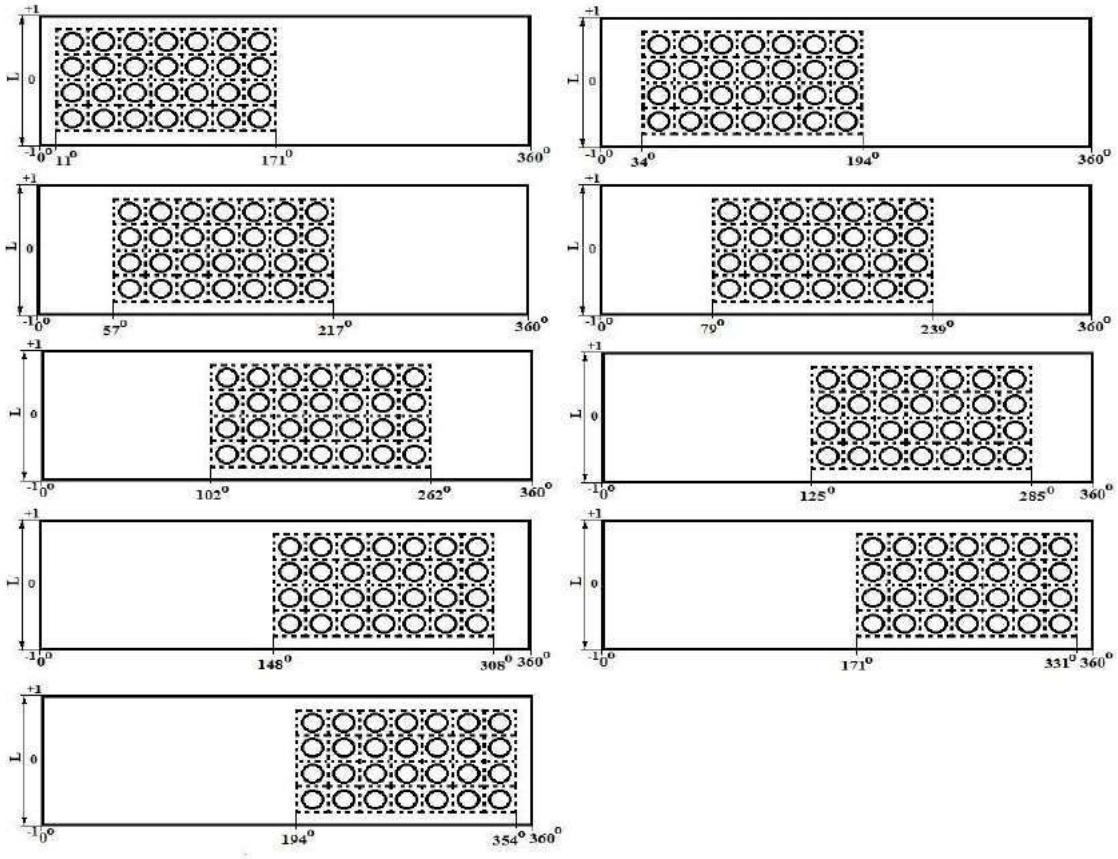 Fig. 4: Different Configurations of Partially Textured Two-Lobe Journal Bearing
Surface texturing introduces alterations in fluid-film pressure distribution, as depicted in Fig. 5. In the context of hydrodynamic lubrication, pressure is primarily generated near the region of minimum fluid-film thickness or clearance, while it reaches its lowest point at the area of maximum clearance or film thickness. In a two-lobe journal bearing, two pressure profiles form due to the dual fluid films—each for upper and lower lobes.
{"image_source":{"path":"images/ad43c2096b395cedccd6601dc121235f770969af41e2b55259016ecb26bf941e.jpg"},"content":"","chart_caption":[{"type":"text","content":"Fig. 5: Circumferential Fluid-Film Pressure at the Axial Mid Plane ("},{"type":"equation_inline","content":"\beta=0.0"},{"type":"text","content":") for Bearing Configurations at "},{"type":"equation_inline","content":"\varepsilon=0.3"}],"chart_footnote":[]}
Load Carrying Capacity ( )
Fig. 6 shows the variation in load carrying capacity for smooth and textured journal bearings, plotted against the location of textures on the bearing surface in the circumferential direction. Notably, the load carrying capacity of partially textured journal bearings reaches its maximum improvement when the textures are positioned within the pressure built-up region spanning from to in the circumferential direction, covering the entire axial direction. This improvement is in comparison to the load carrying capacity of smooth journal bearings. Similar findings have been reported by Singh & Awasthi [24]. For a specific dimple depth of 0.16, there is an 18.90% increase in the load carrying capacity as compared to a smooth journal bearing.
Maximum fluid-film pressure ( )
Fig. 7 illustrates the variation in maximum fluid-film pressure ( ) for both smooth and textured journal bearings, plotted against the location of textures on the bearing surface in the circumferential direction. It is noted that the maximum fluid-film pressure of partially textured journal bearings exhibits an improvement when the textures are positioned within the pressure built-up region spanning from to in the circumferential direction, covering the entire axial direction. This improvement is in comparison to the maximum fluid-film pressure of smooth journal bearings. Similar results have been reported by Singh & Awasthi [24]. For a specific dimple depth of 0.16, there is a remarkable 157.78% increase in the value of maximum fluid-film pressure ( ) when the textures are created in the region of , as compared to a smooth journal bearing.
Attitude angle (Φ)
Fig. 8 presents the variation in the attitude angle ( ) for both smooth and textured journal bearings, plotted against the location of textures on the bearing surface in the circumferential direction. It is observed that the attitude angle ( ) of partially textured journal bearings reaches its minimum value when the textures are positioned within the pressure built-up region ranging from to in the circumferential direction, covering the entire axial direction. This minimum value indicates that the partially textured journal bearing exhibits greater stability when the textures are created within the zone of , compared to a smooth journal bearing. For a specific dimple depth of 0.16, there is a 9.79% decrease in the value of attitude angle for the textured journal bearing, in comparison to the smooth journal bearing.
Lubricant end flow ( )
Fig. 9 depicts the variation in lubricant end flow for both smooth and textured journal bearings, plotted against the location of textures on the bearing surface in the circumferential direction. It is noted that the lubricant end flow of partially textured journal bearings achieves its maximum value when the textures are positioned within the pressure built-up region spanning from to in the circumferential direction, covering the entire axial direction. This maximum value indicates that the partially textured journal bearing exhibits a higher lubricant end flow compared to the smooth journal bearing. Similar results have been reported by Singh & Awasthi [90]. For a specific dimple depth of 0.16, there is a significant 28.50% increase in the value of lubricant end flow compared to the smooth journal bearing.
Fluid-film friction coefficient ( )
Fig. 10 illustrates the variation in the fluid-film friction coefficient ( ) for both smooth and textured journal bearings, plotted against the location of textures on the bearing surface in the circumferential direction. It is observed that the fluid-film friction coefficient ( ) of partially textured journal bearings reaches its minimum value when the textures are positioned within the pressure built-up region ranging from to in the circumferential direction, covering the entire axial direction. This minimum value indicates that the partially textured journal bearing experiences reduced fluid-film friction compared to the smooth journal bearing. It demonstrates that the flow of lubricant is more efficient in the case of a partially textured journal bearing when the textures are created within the zone of . For a specific dimple depth of 0.16, there is a remarkable 119.36% decrease in the value of the fluid-film friction coefficient ( ) for the textured journal bearing, compared to the smooth journal bearing.
4.1 Fluid-Film Stiffness Coefficients
In general, a higher stiffness coefficient indicates a bearing with greater stiffness capable of supporting heavy loads without excessive deflection. The presence of textures on the bearing surface can significantly influence the stiffness coefficients. When textures promote hydrodynamic lubrication, they contribute to increasing the stiffness coefficients. On the other hand, textures that hinder lubrication can lead to a decrease in stiffness. This is because hydrodynamic lubrication helps maintain a thin film of lubricant between the journal and bearing surfaces, reducing friction, wear, and increasing stiffness. Fig. 11 demonstrates the impact of texture location on the fluid-film stiffness coefficient in the horizontal direction of a two-lobe journal bearing. It is observed that the value of the fluid-film stiffness coefficient in the horizontal direction increases by 38.45% when the textures are created within the region of in the circumferential direction, covering the entire axial direction, compared to a smooth journal bearing.
Similarly, the texture on the bearing surface can be designed to achieve the desired stiffness coefficient in the vertical direction. This can be accomplished by optimizing the distribution of surface textures to enhance the contact area between the journal and the bearing surface. Fig. 12 illustrates the effect of texture location on the fluid-film stiffness coefficient in the vertical direction of a two-lobe journal bearing. It is noted that the value of the fluid-film stiffness coefficient in the vertical direction increases by 7.33% when the textures are created within the region of in the circumferential direction, covering the entire axial direction, compared to a smooth journal bearing. Surface textures tend to enhance the stiffness coefficient in the vertical direction because they provide additional contact area between the journal and the bearing surface. This increased contact area requires a higher force to move the journal vertically, resulting in a higher stiffness coefficient.
4.2 Fluid-Film Damping Coefficients
Surface textures can have a significant effect on the damping coefficients of a two-lobe journal bearing. In a journal bearing, the damping coefficients are affected by the flow of lubricant within the bearing. Fig. 13 illustrates the impact of texture location on the fluid-film damping coefficient in the horizontal direction of a two-lobe journal bearing. It is observed that the value of the fluid-film damping coefficient in the horizontal direction increases by 1.81% when the textures are positioned within the region of in the circumferential direction, covering the entire axial direction, compared to a smooth journal bearing. The introduction of textures on the bearing surface can affect the flow of lubricant, thereby influencing the damping coefficient. These textures can enhance the flow of lubricant and promote the formation of hydrodynamic pressure, which is crucial for damping vibration.
In general, the vertical damping coefficient of a journal bearing is affected by the oil film thickness and the frictional losses in the bearing. Surface textures can affect the oil film thickness and distribution, and therefore the damping coefficient. Fig. 14 presents the impact of texture location on the fluid-film damping coefficient in the vertical direction of a two-lobe journal bearing. It is observed that the presence of textures on the bearing surface leads to a reduction in the value of the fluid-film damping coefficient in the vertical direction. The specific decrease in the damping coefficient would depend on the exact texture configuration and location. The presence of textures might reduce the ability of the bearing to retain and distribute oil effectively, and leading to increased friction and reduced damping.
4.3 Critical mass
Fig. 15 shows the effect of texture location versus critical mass of a two-lobe journal bearing. When a texture is added to the surface of a journal bearing, it creates a pattern of small grooves or ridges that can enhance the bearing's ability to retain lubrication and reduce friction. This can increase the load capacity of the bearing, allowing it to support a higher mass. It is noticed that the value of critical mass of a journal is increased by an amount of 29.288% when the surface textures are located in the zone of in the circumferential direction and over the entire axial direction in comparison to smooth bearing. A careful design and testing are necessary to ensure optimal performance of the bearing with the texture in the desired location.
4.4 Threshold Speed
Fig. 16 shows the effect of texture location versus threshold speed of a smooth/textured two-lobe journal bearing. It is noted that the presence of textures on the bearing surface at proper location can increase the threshold speed of a journal bearing. The reason being that the addition of texture to the bearing surface can increase its load capacity, which may allow it to operate at higher speed without failing. For a specific eccentricity ratio 0.3 and dimple depth 0.16, the value of threshold speed of a journal bearing is increased by an amount of 3.19% when the surface textures are located in the zone of in the circumferential direction and over the entire axial direction in comparison to smooth bearing.
4.5 Whirl Frequency Ratio
Fig. shows 17 the effect of texture location versus whirl frequency ratio of a smooth/textured two-lobe journal bearings. The whirl frequency ratio of a two-lobe journal bearing is influenced by the location and geometry of the texture. The texture location can affect the whirl frequency ratio by altering the oil film flow, pressure distribution, and contact area between the journal and bearing. The simulation results indicate that the value the whirl frequency ratio is found minimum when the textures are created in the circumferential zone of and over the entire axial direction at eccentricity ratio 0.3 and dimple depth 0.16 as compared to smooth bearing. This is because of the reason that the texture located at on the bearing surface may reduce the stiffness of the bearing and increases the amplitude of the shaft motion, leading to a lower whirl frequency ratio. Therefore, it is essential to conduct a thorough analysis to determine the optimal texture location and geometry for a specific application.
{"image_source":{"path":"images/477fc122713394f0043349437a7ab351ee58777f96fada628c322b9b2715e44c.jpg"},"content":"","chart_caption":[],"chart_footnote":[]} {"image_source":{"path":"images/4951f5d3ffaf65bba3030cd0cd8529ca77a9ecbeda17df226be9e7bcedf95b74.jpg"},"content":"","chart_caption":[{"type":"text","content":"Fig. 6: Load Carrying Capacity Versus Texture Location in Circumferential Direction"}],"chart_footnote":[]}
{"image_source":{"path":"images/85b0d078036e788d27b398f839a6665de251f5d045ab9a51d3a1f0793c1dc4c0.jpg"},"content":"","chart_caption":[{"type":"text","content":"Fig. 7: Maximum Fluid-Film Pressure Versus Texture Location in Circumferential Direction"},{"type":"text","content":"Fig. 8: Attitude Angle Versus Texture Location in Circumferential Direction"}],"chart_footnote":[]} {"image_source":{"path":"images/32e4b44904a7d58a9e672141387437917f3a24d78775e87f78cb45dae9c9c026.jpg"},"content":"","chart_caption":[],"chart_footnote":[]}
{"image_source":{"path":"images/1966274328feea0c124f9ddd7bbbcf6b84b4c6650e82530ad4c12d3e9896089f.jpg"},"content":"","chart_caption":[{"type":"text","content":"Fig. 9: Lubricant End Flow Versus Texture Location in Circumferential Direction"}],"chart_footnote":[]} {"image_source":{"path":"images/f043614bd83155033b2d17eec068c98a58426e379e23f20a1095165ef7e00986.jpg"},"content":"","chart_caption":[{"type":"text","content":"Fig. 10: Fluid-Film Friction Coefficient Versus Texture Location in Circumferential Direction"},{"type":"text","content":"Fig. 11: Fluid-Film Stiffness Coefficient in Horizontal Versus Texture Location in Circumferential Direction"}],"chart_footnote":[]}
{"image_source":{"path":"images/1cd19650b56a31941e97bbcc114cd0cb3de1819ea9513f9499386d3cb458127e.jpg"},"content":"","chart_caption":[],"chart_footnote":[]} {"image_source":{"path":"images/6c6fcb88ff2f9bc6ca7719e52f09349c82d874a801f516065e5ac5a05bd54d31.jpg"},"content":"","chart_caption":[{"type":"text","content":"Fig. 12: Fluid-Film Stiffness Coefficient in Vertical Versus Texture Location in Circumferential Direction"}],"chart_footnote":[]}
{"image_source":{"path":"images/ccab896db4a6126080f05fc78e0bdc4667c93ee169f4de4025266e4f0ef84718.jpg"},"content":"","chart_caption":[{"type":"text","content":"Fig. 13: Fluid-Film Damping Coefficient in Horizontal Versus Texture Location in Circumferential Direction"},{"type":"text","content":"Fig. 14: Fluid-Film Damping Coefficient in Vertical Versus Texture Location in Circumferential Direction"}],"chart_footnote":[]} {"image_source":{"path":"images/8520f19e20ed858da476220eff9a27798ba1bf740d2e3ea499605a9507a82212.jpg"},"content":"","chart_caption":[],"chart_footnote":[]}
{"image_source":{"path":"images/a8a8128833fb748c476645b2e94065a2a1cd63765137b00ddf2345d13c268c36.jpg"},"content":"","chart_caption":[{"type":"text","content":"Fig. 15: Critical Mass Versus Texture Location in Circumferential Direction"}],"chart_footnote":[]} {"image_source":{"path":"images/3155392b87c95da4105d563337e3c5fbd557d8746f88e739cde6b80258796d9f.jpg"},"content":"","chart_caption":[{"type":"text","content":"Fig. 16: Threshold Speed Versus Texture Location in Circumferential Direction"},{"type":"text","content":"Fig. 17: Whirl Frequency Ratio Versus Texture Location in Circumferential Direction"}],"chart_footnote":[]}
V. CONCLUSIONS
This theoretical research paper delved into the critical aspects of optimizing texture position in two-lobe journal bearings to enhance both dynamic stability and operational performance. Through a comprehensive exploration of the underlying principles and governing equations, this study has contributed valuable insights to the field of tribology and mechanical engineering. Bases on the results presented, the following conclusions can be drawn:
- The study underscores the importance of placing surface textures strategically within bearing clearance zones. Such placement significantly influences the dynamic behavior of the bearing system, reducing instabilities caused by operational variations like load
Conflict of Interest
The authors declare no conflict of interest.
Ethical Approval
Not applicable
Data Availability
The datasets used in this study are openly available at [repository link] and the source code is available on GitHub at [GitHub link].
Funding
This work did not receive any external funding.
References
Cite this article
Related Research


Special Issue
Launch a focused special issue to highlight research, emerging trends, and expert insights in your academic field.
