


IntelliPaper
Abstract
The research focuses on the adaptation of greenhouses for farming, emphasising its positive feedback as a feasible and sustainable option for year-round crop cultivation. The research involves a system that utilises sensors connected to a microcontroller to monitor greenhouse conditions. The sensors measure temperature, humidity, soil moisture, light intensity, and water levels. The system is powered by AC to DC supply, with additional features like a fan to cool the environment and a bulb responding to natural light intensity. The collected data is sent to a webpage for remote monitoring through the Serial Peripheral Interface Flash File System (SPIFFS). The study encompasses two main aspects: sensing and regulation, and transmitting real-time data for remote monitoring.
Explore Digital Article Text
I. INTRODUCTION
Many food crops depend on certain weather conditions to grow and produce fruits. The effects of climate change pose a serious threat to the agriculture industry in tropical nations. This is due to variations in weather patterns, which affect crop yields and productivity in these regions (Chemura et al., 2020).
Climate change is inherently dangerous to crop productivity. Temperature has a big impact on how quickly plants grow, thus if temperatures rise and shorten the developmental stages of determinate crops as a result of climate change, the yields of that species would probably decline (Crawford and Wheeler, 2009).
Many farmers and investors in the farming sector of Ghana's economy experience many hardships due to unprecedented changes in weather conditions. Due to Ghana's dependence on rain-fed agriculture and sensitivity to drought, as well as the fact that less than of the country's agricultural land is irrigated, changing climatic circumstances constitute a danger to the sector's growth (Chemura et al., 2020b). Several farmers have lost a large part of their crops and produce to unfavourable climatic conditions. This happens mostly because most farmers are unable to adequately monitor and regulate the conditions their crops are exposed to whiles on the farm (Pusatkar and Gulhane, 2016).
Some farmers try to undertake proper measures to ensure their crops do not fall prey to poor weather and neglect. However, for much of the work done to ensure the crops on the farms are exposed to the best of conditions, manual labour is employed. Most research into the agricultural sector aims to significantly reduce the employment of manual labour in the monitoring and regulation of farm conditions. Employing manual labour as a means of monitoring and regulating farm conditions can prove to be very unrewarding due to poor judgment and unreliability (Gallardo and Sauer, 2018).
In the case where manual labour is acquired, there still exists a significant cost in training these personnel in the use of relevant technologies. There is also a lot of cost involved in acquiring and maintaining high-end technologies that ultimately produce minimum results (Virk et al., 2020). The objective of this research is to design an experimental model of a greenhouse that can regulate the internal temperature and light, monitor the soil moisture content of the greenhouse, and send the data to a designed webpage to facilitate remote monitoring.
II. RELATED WORKS
The adaptation of greenhouses as a means of farming has recorded a lot of positive feedback. Precision agriculture, data processing, and smart farming advancements are driving a revolutionary change in closed-field agriculture. From simple covered greenhouse constructions, protected cultivations have developed to cutting-edge plant factories that maximise both plant and labour output (Shamshiri et al., 2018). To manage the local climate and grow crops all year long, even in harsh outside circumstances, greenhouse agriculture is seen to be a feasible alternative and sustainable option that can address the coming food crisis. It is believed that Internet of Things (IoT) technologies, including smart sensors, devices, network topologies, big data analytics, and intelligent decisions, will answer greenhouse farming problems, including local climate control in greenhouses, crop growth monitoring, crop growth monitoring, crop harvesting, and other issues (Rayana et al., 2020).
Doshi et al., (2019) proposed a technology which can alert farmers of the conditions of their crops by generating messages on varied platforms. The technology will help farmers by giving them access to real-time data from the farms (temperature, humidity, soil moisture) so they can take the necessary steps to practise smart farming, improve crop yields, and conserve resources (water, fertilizers). The device described in this paper makes use of the ESP32 Node MCU, a breadboard, the DHT11 Temperature and Humidity Sensor, the Soil Moisture Sensor, the SI1145 Digital UV Index/IR/ Visible Light Sensor, jumper wires, LEDs, and a serial monitor to display live data feed. It also uses the Blynk Mobile app.
Nicolosi et al., (2017) also developed a similar system. This work demonstrates an adaptive control system designed to govern the microclimate in a greenhouse by combining creative soft computing approaches. Specifically, a neural network strategy has been suggested to anticipate the greenhouse's climatic behaviour, while a parallel fuzzy scheme approach is used to modify the fan-air coil's speed and temperature. Due to the system's capacity to make immediate decisions on both observed variables and anticipated climatic change, the suggested integrated method offers greater management of greenhouse climatic conditions.
Another related project is that of Kodali et al., (2016) on the theme, "IoT based Smart Greenhouse". The model of a smart greenhouse provided by this work enables farmers to carry out farm work automatically without relying heavily on manual inspection. As a closed structure, a greenhouse shields plants from harmful weather elements like wind, hail, ultraviolet rays, and insect and pest attacks. Agricultural fields are irrigated using automated drip irrigation, which runs in line with the soil moisture threshold set appropriately to provide the plants with the ideal amount of water. Drip irrigation techniques may be used to apply the right quantities of nitrogen, phosphorous, potassium, and other minerals based on information from the soil health card. An ultrasonic sensor is used to measure the present water level before building the appropriate water management tanks and adding water to them. Growing lights are used at night to provide plants with the necessary wavelength of light. Humidity and temperature sensors, together with a fogger, are used to regulate temperature and air humidity.
Short Message Service (SMS) from Subscriber Identity Module (SIM) is used to regulate a tube well. Beehive boxes are used for pollination and ultrasonic sensors are used to monitor the boxes, measure the honey, and send emails to the purchasers when the boxes are full. Additionally, the data gathered from storage containers is transferred to a cloud service (Google Drive) and can be sent to an online retailer.
III. GREENHOUSE AUTOMATION TECHNOLOGIES
Automation technologies used in greenhouses include agricultural automation for crop growth, remote monitoring and control systems, and Artificial Intelligence (AI) technology. According to Levonevskiy, et al. (2023), Agricultural automation aims to reduce time and cost of crop production and minimize human errors. A study conducted by Moreno, et al. (2023) showed how remote monitoring and control systems utilize voice command recognition and mathematical models for analysing environmental parameters. AI technology is used for optimizing crop yields, water and fertiliser use efficiently, pest and disease control, and energy management (Maraveas, 2022). Robotic systems, bio-inspired algorithms, and image signal processing are employed for various greenhouse processes (Starikov, Gribanov and Starikova, 2022). Additionally, AI-based irrigation and soil fertiliser application have shown higher returns on investments and resources efficiently. Combined irrigation systems, such as low-volume drip and aerosol irrigation, are also used, with electrochemical activation of water expanding the technological modes of irrigation. These automation technologies aim to improve efficiency, reduce costs, and enhance agricultural sustainability in greenhouse farming.
IV. REMOTE MONITORING SYSTEMS
Remote monitoring systems play a crucial role in greenhouse management by providing real-time monitoring and control of environmental parameters. According to Bo (2023) and Zhu et al (2022), in their studies, emphasised how these systems allow farmers to remotely monitor crop growth and adjust environmental factors such as temperature, soil moisture, and light intensity. By using IoT technology and deep learning algorithms, intelligent agriculture monitoring systems can effectively collect and analyse data on greenhouse temperature, carbon dioxide, light, and other environmental factors (Agilesh Saravanan et al., 2023). The data collected can be stored and accessed through cloud platforms, enabling farmers to monitor and control their greenhouses from anywhere (Chen et al., 2022). Additionally, remote monitoring systems can notify farmers of any anomalies or issues through mobile applications, allowing for timely intervention (Mellit et al., 2021). These systems improve efficiency, reduce management costs, and enhance the quality of crop production in smart greenhouses. The concept of remote monitoring and control is transforming greenhouse farms operations across the globe. This innovative technology allows the farmer to manage and oversee greenhouse processes, assets, and systems from a distance, offering unparalleled convenience, efficiency, and insight.
V. COMPONENTS OF GREENHOUSE AUTOMATION
This research consists of a system that senses the conditions within the enclosure of the greenhouse and sends live data to the webpage for viewing using the Serial Peripheral Interface Flash File System (SPIFFS). The research can be considered within two distinct contexts: Sensing and regulation and transmitting live data to enable remote monitoring. The conditions within and immediately around the greenhouse are measured using designated sensors connected to the ESP32 Microcontroller. These sensors include a DHT11 Temperature and Humidity sensor for determining the environment's temperature and humidity. It also includes a soil moisture sensor to detect the amount of moisture within the soil, and a light sensor to turn on or off the lights depending on the intensity of the natural light within the surroundings of the greenhouse. There is also a water level sensor to keep record of the level of the water in the irrigation tank. The system is powered by an AC to DC power supply. The system has a fan and bulb inside the greenhouse. The fan is turned on when the temperature exceeds a limit of C to help cool the environment. The Bulb is turned on when the natural light in the immediate environment of the greenhouse drops below a certain percentage intensity. The data received from the sensors are sent to the microcontroller which is then rerouted and sent to the webpage for monitoring. This is done using the SPIFFS server.
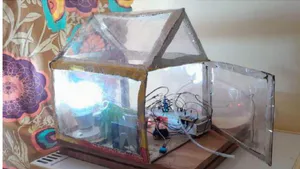
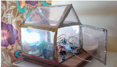
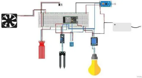
The Prototype of the greenhouse mimics the functioning of a regular greenhouse. Typical crops that can be grown using this system include regular-sized fruit-bearing crops as well as vegetables. The greenhouse can be mounted in any location with adequate sunlight and ventilation. Figure XX shows the experimental model of the greenhouse automation.
The setup was done by connecting different devices with specific purposes which come together to ensure the system works together as a unit to achieve the objective of the research. The project aims to automate the regulation of the conditions within the greenhouse using sensors and fuzzy logic. Fig xx shows the hardware setup of the greenhouse. The setup was done using three principal components:
i. The ESP32 Microcontroller
ii. Breadboard
iii. Jumper Wires.
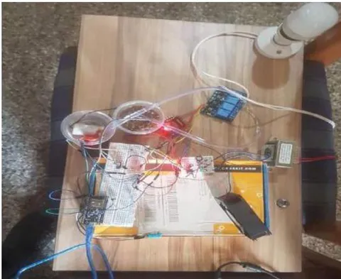
The Microcontroller, the breadboard and the wires are used to ensure that the sensors and other devices within the system interface with each other successfully. The Microcontroller has limited pins and connecting all the devices directly may overcrowd the setup. The breadboard serves as an extension for the microcontroller to allow for better connections while ensuring a closed loop. It fundamentally ensures a successful basic circuit.
The ESP32 Microcontroller processes the data received from the sensors to activate the necessary devices using its processor. It has preinstalled firmware that allows it to coordinate communication between the peripherals.
The Jumper wires are a solderless means of connecting the microcontroller and the other components of the system.
VI. CIRCUIT CONNECTION
The main power source of the system was a DC power source adapted from an AC/DC power converter. To ensure that power is supplied to the entire system, the power from the converter is connected to the breadboard and the other components including the microcontroller is connected to the power strip on the breadboard. The ground however is connected from the ESP32 ground pin to the breadboard. The other sensors and devices connect to the ground from the extension on the breadboard. All these connections are done with the help of the jumper wires.
6.1 DHT11 Temperature and Humidity Sensor
i. The signal pin of the DHT11 temperature and Humidity sensor is connected to digital pin 14 on the ESP32 microcontroller.
ii. The Ground pin is also connected to the Ground (-) bus on the breadboard.
iii. The power is tapped from the breadboard by connecting the VCC pin to the Positive (+) bus on the breadboard.
6.2 Moisture Sensor
i. The moisture sensor was also connected to pin 35 on the microcontroller.
ii. The Ground pin is also connected to the Ground (-) bus on the breadboard.
iii. The power is tapped from the breadboard by connecting the VCC pin to the Positive (+) bus on the breadboard.
6.3 Water Sensor
i. The water sensor was also connected to pin 34 on the microcontroller.
ii. The Ground pin is also connected to the Ground (-) bus on the breadboard.
iii. The power is tapped from the breadboard by connecting the VCC pin to the Positive (+) bus on the breadboard.
6.4 Photosensor (LDR)
i. The photosensor was also connected to pin 32 on the microcontroller.
ii. The Ground pin is also connected to the Ground (-) bus on the breadboard.
iii. The power is tapped from the breadboard by connecting the VCC pin to the Positive (+) bus on the breadboard.
6.5 Bulb
i. The bulb channel signal was also connected to pin 33 on the microcontroller.
ii. The Ground pin is also connected to the Ground (-) bus on the breadboard.
The power is tapped from the breadboard by connecting the VCC pin to the Positive (+) bus on the breadboard.
6.6 Fan
i. The Fan output pin was also connected to pin 25 on the microcontroller.
ii. The Ground pin is also connected to the Ground (-) bus on the breadboard.
iii. The power is tapped from the breadboard by connecting the VCC pin to the Positive (+) bus on the breadboard.
6.7 Pump
i. The pump output pin was also connected to pin 12 on the microcontroller.
ii. The Ground pin is also connected to the Ground (-) bus on the breadboard.
The power is tapped from the breadboard by connecting the VCC pin to the Positive (+) bus on the breadboard.
VII. IMPLEMENTATION AND TESTING
i. The system employs the use of several sensors in the development process. These sensors are responsible for measuring certain variables and act indirectly as actuators. When the readings recorded correspond with certain predetermined values, particular devices within the greenhouse are activated. The microcontroller has a set of preloaded functions that help to control the sequencing ordered by the logic implemented by user-inputted instructions. The main processes of the system include;
ii. The reading of temperature and humidity values within the greenhouse. The readings are sent to the microcontroller for processing. The value of temperature is stored and analysed using predefined fuzzy logic. If the value of temperature goes beyond C, the fan is activated. The logic at that stage iterates till the fan goes off when the temperature falls below the threshold.
iii. Similar to the other DHT11, the soil moisture sensor reads the moisture content of the soil and transmits that data to the microcontroller. The microcontroller processes the data and implements similar logic as the one performed on the data from the temperature sensor. The readings were recalibrated and expressed as a percentage. When the moisture content falls below the lower limit of 20%, the DC pump is automatically activated. It pumps water into the soil. The pump is activated for as long as the moisture content of the soil is below the lower limit and goes off when it detects moisture above the 20% minimum value.
iv. The Photosensor detects the intensity of light in the surrounding environments of the greenhouse. Similar to the soil moisture sensor, its readings were expressed as a percentage. The logic was to activate the bulb once the surrounding light dropped in intensity below the minimum value and turn off the bulb once the intensity of light rises above the given value.
v. The water sensor was also used to measure the level of water in the tank. This is to make sure the farmer always knows when to refill the tank to ensure the crops are always irrigated.
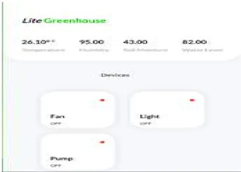
vi. All the data transmitted to the microcontroller are processed and delivered to the webpage through the Wi-Fi module. The data displayed on the webpage is live. This means the farmer would have real-time data concerning the state of the greenhouse.
vii. The system iterates this process as long as it is powered and connected to a network.
VIII. DATA ANALYSIS AND DECISION SUPPORT
The conditions necessary for the activation of the devices within the greenhouse were stimulated to ensure their efficiency. The devices responded positively to the changes in the conditions accurately. Figure xx shows the webpage displaying the data from the sensors and the state of the devices in desktop mode.
VIII. CONCLUSION
The objective of the project was to develop a prototype of a greenhouse that had automated functions to regulate the conditions of the greenhouse. This was achieved using an ESP32 microcontroller and several sensors as well as some regulatory devices. The system is fully automated when connected to a power source and a network. To enable the farmer to monitor the state of the greenhouse, the data is transmitted to the webpage accessible on the network. It is therefore rational to say that the system is operational and can be modified and enhanced to perform the automation on a larger and more effective scale.
Several issues can be addressed to ensure the system is fully operational. The power source can be changed to a solar source. This will enable the system to be set up in locations where electricity is not accessible. The SPIFFS method can also be upgraded to a larger network to allow monitoring from farther locations.
Conflict of Interest
The authors declare no conflict of interest.
Ethical Approval
Not applicable
Data Availability
The datasets used in this study are openly available at [repository link] and the source code is available on GitHub at [GitHub link].
Funding
This work did not receive any external funding.
References
Cite this article
Related Research

Special Issue
Launch a focused special issue to highlight research, emerging trends, and expert insights in your academic field.