


Abstract
The primary aim of this research is to investigate the structural uses of an aluminium alloy with a composite plate made of graphene in launch vehicle fuel tanks. To evaluate the viability and performance of the composite plate in this application, finite element analysis (FEA) modelling is used. The study aims to analyse the composite plate's mechanical behaviour, thermal characteristics, and structural integrity under various loading scenarios, such as mechanical and thermal loads, stress, and strain. The outcomes of the FEA model are compared with the materials currently used in the external fuel tanks of launch vehicles. A cost analysis of the production process is also carried out to determine whether using the graphene-based composite plate is economically feasible. The study intends to provide light on the benefits, difficulties, and constraints related to the structural components of launch vehicle fuel tanks made of graphene-based composites. The results of this study have the potential to advance the discipline of aeronautical engineering and establish the framework for upcoming advances in materials science and design optimisation for launch vehicle applications.
Explore Digital Article Text
I. INTRODUCTION
The aerospace sector is continually looking for novel ways to improve the effectiveness and performance of launch vehicles. To retain structural integrity during launch and space missions, fuel tanks, as a crucial component of these vehicles, require materials that can withstand extreme conditions. Due to its remarkable mechanical qualities, lightweight, and thermal conductivity, graphene-based composites have recently attracted increasing interest in aircraft applications. Finite element analysis (FEA) modelling is the primary study tool to examine the viability of utilising an aluminium alloy with a graphene-based composite plate for structural applications in the fuel tanks of launch vehicles.
The materials currently used to build fuel tanks for launch vehicles have limitations, including weight, corrosion resistance, and mechanical qualities. To overcome these obstacles and deliver improved performance, it is necessary to investigate new materials and technologies. It offers enormous promise to improve structural grades to incorporate graphene, a two-dimensional carbon material, into an aluminium alloy matrix. Graphene has remarkable mechanical, thermal, and electrical properties. This study's primary objective is to evaluate the viability of using a composite plate made of graphene and aluminium for the structural use of fuel tanks in launch vehicles. This study uses FEA modelling to assess the suggested composite material's mechanical behaviour, performance, and durability under various situations, such as heat loads, mechanical stresses, and strain.
This research involves a comprehensive literature review on the FEA modelling of aluminium alloys with graphene-based composites for aerospace structural applications. The study consists of developing a model utilising the FEA technique and validating it against experimental data to ensure accuracy and dependability. Numerous analyses will evaluate the composite material's performance under various loading conditions, including thermal, stress, and strain studies.
The novel concept of this research is the incorporation of graphene-based composites into the structural design of launch vehicle fuel containers. This novel approach can significantly enhance strength, weight reduction, and corrosion resistance compared to conventional materials. In addition, FEA modelling provides a cost-effective and efficient method for evaluating the feasibility and performance of the proposed composite material before conducting physical tests.
1.1 Problem Description
Launch vehicles are crucial to space exploration, requiring high-performance materials that withstand extreme conditions. Their materials limit the launch vehicle fuel tank's weight, strength, and thermal stability. The above considerations have prompted studying alternate materials that might increase launch vehicle efficiency and safety.
Due to its strength-to-weight ratio, aero planes use aluminium alloys extensively. However, modern space travel requires materials with remarkable properties beyond ordinary alloys. Graphene-based composites' mechanical, thermal, and electrical characteristics make them intriguing materials. Graphene in aluminium alloys may improve launch vehicle fuel tanks. However, this idea raises essential questions. The structural usage of an aluminium alloy and a graphene-based composite plate in launch vehicle fuel tanks is complex and requires a detailed investigation. The modelling and assessment of composite materials under various conditions might benefit from Finite Element Analysis (FEA) models. However, several criteria must be considered to successfully implement this revolutionary material notion. In space exploration, launch vehicles need innovative materials to survive harsh temperatures and operate well. Current launch vehicle exterior fuel tank materials are limited in weight, strength, and thermal stability. This has led to researching alternate materials that may improve launch vehicle efficiency and safety.
The strength-to-weight ratio of aluminium alloys makes them popular in aircraft. However, contemporary space exploration requires materials with superior qualities to previous alloys. Due to their mechanical, thermal, and electrical properties, graphene-based composites seem promising. Incorporating graphene into aluminium alloys might improve launch vehicle fuel tanks, but it poses numerous essential problems.
The viability of using an aluminium alloy and a graphene-based composite plate for launch vehicle fuel tank structural purposes is complex and requires more research. To simulate and evaluate these composite materials under different situations, Finite Element Analysis (FEA) modelling is helpful. To apply this innovative material idea successfully, many factors must be addressed.
1.2 Project Aim
Investigation of the feasibility of using aluminium alloy with a graphene-based composite plate for structural application in the fuel tanks of launch vehicles through FEA modelling.
1.3 Project Objectives
Literature review of FEA modelling of the aluminium alloy with a graphene-based composite plate for the launch vehicle external fuel tank structural application.
Developing a model and validating it against experimental data.
Analysing composite plates under various conditions such as thermal, mechanical loads, stress and strain, etc.
Analysing the external fuel tank of the launch vehicle under various conditions.
Comparing results with the current material used for the external tank of the launch vehicle.
Identifying any challenges or limitations.
II. LITERATURE REVIEW
2.1 Material
Aluminium metal matrix composites (MMCs) have been thoroughly researched for wear across several operating settings. The authors examined how average load, sliding velocity, sliding distance, and reinforcements impact the composite's wear rate and coefficient of friction (COF). Delamination, adhesive wear, abrasive wear, and fretting are well-studied. Stir casting, powder metallurgy, and friction stir processing have produced aluminium MMCs. Production methods depend on composite material qualities. Stir casting is inexpensive, but friction stir processing increases microstructural and mechanical characteristics. Pin-on-disc wear experiments measured aluminium MMCs' wear rate and COF. SEM examined the worn surface's shape and causes.
Powder metallurgy, stir casting, and squeeze casting have been studied to distribute 2D graphene nanoplatelets into the matrix uniformly. The hardness, tensile strength, and ductility of Metal Matrix Composites (MMCs) are significantly affected by 2D–graphene nanoplatelets dispersion. The proper distribution of 2D-graphene nanoplatelets can increase grain refinement and stable intermetallic phases, improving metal matrix composite's (MMCs) mechanical properties.
Multiple investigations have investigated the effects of graphene incorporation into an aluminium matrix. It has been observed that incorporating graphene improves the composite's mechanical properties up to a certain point. Among the reinforcement mechanisms are effective load transfer via Orowan looping of nanoparticles, load transfer from the aluminium matrix to graphene, dislocation strengthening due to coefficient mismatch, and grain refinement. Several fabrication techniques have been investigated, with powder metallurgy being the most common technique for obtaining a decent graphene dispersion within the matrix.
Despite mechanical exfoliation and chemical reduction, graphene with outstanding properties is still challenging to produce. Authors found that nanocomposites using graphene fillers have higher modulus and tensile strength. Graphene fillers' distribution inside the polymer matrix has also been an issue, driving research to optimise interfacial interactions and achieve homogenous dispersion to reduce agglomeration. To make graphene nanocomposites, researchers have used several methods. To improve graphene compatibility with the polymer matrix, functionalisation is often used. Hybrid fillers, which combine graphene with other nanomaterials like carbon nanotubes or metal oxides, have also been studied to solve graphene's specific restrictions and achieve customisable characteristics. Solution blending, melt mixing, and electrophoretic deposition are also used to incorporate graphene into the polymer matrix.[7]
Direct Digital Manufacturing (DDM) is one novel process for creating GNP-reinforced aluminium matrix composites that is both unique and efficient. DDM uses considerable plastic strain and frictional and deformation methods to generate heat. This synergistic impact promotes dynamic recovery and recrystallisation, uniformly dispersing Graphene Nanoplatelets (GNPs) and forming ultra-fine microstructures. The technology reduces processing time and improves microstructural manipulation. DDM works in many metal matrix composites, demonstrating its versatility and potential. Despite the favourable results of DDM on other metal matrix composites, GNP-reinforced aluminium matrix composite investigations are expected. Direct Digital Manufacturing (DDM) study on the effects of processing factors on these composites' microstructure and mechanical properties must be included. Although specialised studies have explored the mechanical properties of composites, there needs to be more studies on improving strength-ductility, which is critical in real-world applications. This research is relevant to the study's aims. Direct Digital Manufacturing (DDM) of aluminium matrix composites containing Graphene Nanoplatelets (GNP) may solve GNP dispersion and interfacial bonding issues. This work addresses literature gaps and analyses processing parameters to improve composite strength-ductility efficiency and mechanical performance.[8]
Hot extrusion is the primary method for compacting graphene nanosheets and aluminium particles into a billet. Hot rolling then improves the composites' microstructure and mechanical properties. Extrusion-MPHR hybrid deformation improves graphene nanoplatelet dispersion and interfacial bonding, enhancing mechanical properties. GNS content, extrusion parameters, and hot rolling circumstances have been studied in composites' microstructure and mechanical properties. Interfacial reaction products, such as Al4C3, at the interface between aluminium and graphene nanosheets and their impact on the composite material, have also been studied. However, hybrid deformation's unique effect on graphene nanosheet dispersion and interface bonding must be better understood. Graphene nanoplatelets aluminium composites are progressing, although certain areas need additional research and development. First, hybrid deformation's effects on composite grain boundary network distribution and interfacial structure should be studied more. To optimise composites' mechanical properties, these changes must be understood. Despite GNS/Al composite strengthening studies, load transfer strengthening efficiency and interaction with the interfacial structure must be thoroughly evaluated. Interfacial transition zones might increase load transmission during hybrid deformation. A quantitative appraisal needs to be improved.[9]
A prevalent technique is mechanical stir casting, which entails mixing multi-walled carbon nanotubes and Mg (wettability agent) with molten A356 alloy and solidifying. Wu, Chang, Gurkan, and Cebeci utilised the Taguchi method, a robust experimental design, to optimise composite development parameters. They discovered that the quantity of multi-walled carbon nanotubes, magnesium, and duration of mechanical agitation significantly affected the composite's mechanical properties. The role of mechanical agitation in dispersing multi-walled carbon nanotubes within the matrix has been extensively investigated. Wang et al. and Alhawari et al. discovered that mechanical agitation enhanced the homogenous distribution of reinforcement materials within an aluminium matrix. In addition, Mg is frequently used as a wettability agent to improve the hydration and interfacial bonding between multi-walled carbon nanotubes and the aluminium matrix. Bakr et al. reported that adding 0.75% Mg to the liquid enhanced its wettability. Although significant progress has been made in fabricating and characterising multi-walled carbon nanotubes -A356 composites, certain limitations persist. Determining multi-walled carbon nanotubes and Mg content within the matrix continues to be complicated. Moreover, although several studies have investigated the effects of multi-walled carbon nanotube content, mechanical agitation, and Mg on mechanical properties, a comprehensive optimisation strategy is still required to achieve an optimal combination of these parameters.
The distinctive qualities of graphene, such as its two-dimensional flaky structure and substantial surface area, have been highlighted. These qualities make graphene an appealing reinforcing material for aluminium matrices. Graphene reinforcement particles are distributed uniformly despite some investigations reporting grain boundary aggregation at more significant graphene weight percentages. The composites were successfully constructed using hot extrusion and microwave processing processes, which allowed them to satisfy the requirements for structural usage in the super lightweight external fuel tank. This study's specific objectives are to examine the process by which graphene adheres to the aluminium matrix and to assess the impact of various graphene weight percentages on the microstructure and mechanical characteristics of the composite.
Many authors have focused on developing corrosion-resistant coatings for aluminium alloys. Polymer electrolyte oxide (PEO) coatings have gained popularity because of their hardness, thickness, and corrosion resistance. Graphene nanomaterials in coatings have been widely studied for corrosion protection. Graphene's electron-rich structure and colossal surface area make it a promising corrosion inhibitor for metal substrates. Plasma electrolytic oxidation (PEO) coatings have been tested for corrosion resistance utilising graphene. Electrochemical impedance spectroscopy (EIS) and potentiodynamic polarisation curve measurements are routinely used to assess coating corrosion behaviour. The scanning Kelvin probe (SKP) has also been used to compare the Volta potential of coated and uncoated materials, providing microelectrochemical insights into corrosion. Graphene-incorporated PEO coatings' corrosion resistance has been studied. The study has several undiscovered regions. First, no literature compares graphene concentrations and their effects on PEO coating corrosion resistance. Graphene's processes for improving PEO coatings' corrosion resistance still need clarification. Scalability and industrial viability must also be investigated.
The authors have applied FSAM to aluminium-lithium alloys, specifically 2060 Al-Li, the third-generation alloy. FSAM, a solid-state additive manufacturing method, avoids melt-based AM difficulties. The authors used laser-assisted powder bed fusion (L-PBF) to build Al-14Li alloy blocks with fissures and inclusions. They used wire arc additive manufacturing (WAAM) to deposit AA2050 Al-Li alloy with microstructural variations. They examined the laser melting dimension (LMD) of 2A97 Al-Li alloy and found non-uniform microstructures and poor mechanical characteristics. FSAM can produce structurally efficient magnesium alloy components and 7N01-T4 Al alloy with finer and more uniform microstructures and moderately enhanced automatic features. Traditional melt-based AM techniques generally have coarse microstructures and internal flaws due to the melting-solidification cycle. FSAM avoids metallurgical defects during melting and solidification in solid-state additive manufacturing. Compact and fine FSAM granules improve mechanical characteristics. FSAM also causes dynamic recrystallisation during intense plastic deformation and heat input, producing fine equiaxed granules between 2 and 5 m in the nugget zone.
However, despite these advancements, several voids in the existing literature must be addressed. First, more research should be conducted on the combined influence of copper, alumina, and graphene on the properties of aluminium composites. Although individual studies have examined the effects of these components, a comprehensive comprehension of their synergistic interactions still needs to be improved. Fixing this gap is essential for optimising aluminium composites that use multiple reinforcements. More research needs to be conducted on the effects of secondary processes, specifically hot rolling, on the microstructure and properties of aluminium composites. Much research has concentrated solely on the powder metallurgy technique, ignoring the potential improvements that can be attained through subsequent processing stages. It is essential to investigate the effects of hot rolling as a secondary procedure to optimise the properties of aluminium composites and reveal the mechanisms underlying the improvements.
While individual reinforcements have been exhaustively examined, research on hybrid composites that combine multiple mounts is limited. Sometimes, the optimal combination of reinforcement particles and their respective volume fractions for attaining the most significant wear performance is not well-defined. Wear behaviour under varied loads and sliding conditions: The wear behaviour of Al-Si composites under varying loads and sliding velocities requires additional research. Inadequate study of wear mechanisms: It is essential to identify the factors contributing to wear resistance and degradation by thoroughly investigating wear mechanisms in various composites.
Most synthesis methods use dangerous substances or excessive energy, harming the environment. Assessing and managing these impacts is essential for using graphene-based devices. Industrial graphene production is challenging. Scalable, cost-effective technologies like FJH need optimisation and validation to satisfy commercial expectations. Refuse materials for graphene production are untested. Research should find suitable carbonaceous sources and evaluate their environmental impact.
Carbon nanotube yarns have demonstrated repeatable, stable resistance behaviour and low density, making them appropriate for real-time monitoring of composite deformation and fracture propagation. Moreover, incorporating carbon nanotube fibres into an epoxy matrix preserves their flexibility, preventing permanent fractures even after substantial deformations. Authors have also investigated multi-objective optimisation to determine the optimal graphene nanoplatelet distribution pattern and material profile for attaining desirable structural performance goals. CNT-steel composites have demonstrated potential for applications in high-pressure and high-temperature environments requiring anticorrosive and mechanically robust materials. In addition, the improvement of CNT web performance for mode I interlaminar fracture toughness has been identified as a potential area for future research, which may involve amino-functionalization. The use of carbon nanotubes in cementitious composites has the potential to overcome the functional limitations of conventional conductive additives; however, additional research is necessary to assure durability and stability. In addition to experimental characterisation, numerical analysis has been used to examine fracture behaviour, fissure initiation and propagation, and microstructural damage in CNT and graphene composites.
Nanocomposites reinforced with CNTs and graphene have been studied for their mechanical properties and fracture response. Authors have used different polymer matrices to examine many carbon nanotubes (CNT), graphene production, and nanocomposite synthesis methods. Tensile strength, Young's modulus, and fracture toughness have been studied using experimental and computational methods. Authors have studied how carbon nanotube (CNT) and graphene concentration, dispersion, and alignment affect nanocomposites' mechanical characteristics. Since the matrix-CNT-graphene interfacial bonding determines mechanical properties, considerable study has focused on it. Examining nanocomposites' fracture behaviour has included CNT defects, inclusions, and agglomeration. They have used numerical modelling methods to predict nanocomposites' mechanical properties and fracture tendencies. FEA, MD, and micromechanics models are used. Tensile testing, fracture toughness, and interlaminar fracture tests have supported computational results.
Aluminium-graphene nanoplatelet (GNP) composites have been manufactured using numerous methods. Powder metallurgy and hot extrusion evenly distribute graphene nanoplatelets (GNPs) in the aluminium matrix. Spark plasma sintering, hot accumulative roll bonding, and hot rolling have been researched for making these composites. Composites' mechanical and thermal properties have been studied using various processing methods. The series, parallel, Maxwell, Son-Frey, and Russell models have been used to estimate thermal conductivity in these composites. These models assess composites' effective thermal conductivity by considering volume percentage, shape, matrix and reinforcing thermal conductivities. Experimental studies on aluminium composites' mechanical and thermal properties, incorporating graphene nanoplatelets (GNPs), have neglected finite element modelling of heat conductivity. There are few limited element analysis studies predicting these composites' thermal properties. Given the research gap, finite element analysis may be able to accurately estimate the thermal conductivity of aluminium composites, including distributed graphene nanoplatelets (Harichandran et al., 2022).
Stir casting is popular because it evenly distributes reinforcements and bonds the matrix and particles. Stir casting has better reinforcement distribution than other methods, improving mechanical characteristics. Researchers altered weight percentages to determine how SiC and B4C affect aluminium composite characteristics. Studies show a trade-off between mechanical parts and ductility as the B4C level enhances hardness and tensile strength but decreases elongation%.
Based on a literature analysis, graphene nanoplatelets (GNPs) can improve mechanical characteristics in aluminium matrix composites. Correct GNP dispersion during mechanical alloying can improve mechanical behaviour together with sintering optimisation. Composites with extended milling periods and higher GNP concentrations should be more complex. The research also optimises processing settings, investigates graphene shapes, and creates composites for real-world applications to fill gaps in the literature.
Extensive research has demonstrated the potential of GNFs as reinforcing agents in various materials; the investigation of GNFs as supporting agents in metals or aluminium alloys, especially aluminium alloys, still needs to be completed.
The synthesis method and reinforcement material substantially affect Al nanocomposite reinforcing mechanisms and mechanical properties. For and Al-GNP nanocomposites, particle size is a crucial factor in determining their strength and durability. In addition, impurities and the bonding quality between the matrix and reinforcement may play a significant role in the nanocomposite's overall strength.[21]
2.2 FEA on Composite Plate
Numerous ANSYS studies have examined rectangular plate buckling analysis. Hassan and Kurgan evaluated shell and solid plate models to measure buckling prediction accuracy. They stressed the importance of lattice density and found that shell models, notably Shell281, are more realistic for thinner plates. Solid models of solid-shell components, such as Solsh190, were recommended for bigger vessels because they match 3D elasticity theory answers.
Authors have employed various modelling strategies and numerical tools for delamination buckling analysis. The delamination behaviour is simulated using a two-sublimate model in Ansys with eight-node composite shell elements. The two sub-laminates are coupled, and the delaminated region's nodes are left uncoupled. This method provides a practical technique for modelling delaminated composite panels and demonstrates excellent agreement with theoretical predictions and prior research. Despite significant advancements in delamination buckling analysis, certain voids remain. A significant omission is the consideration of eccentricity in loading, particularly for thin panels with close-to-surface delamination. The study in Section 5.2 highlights the significance of this factor and demonstrates that eccentricity substantially affects the distribution of buckling load and strain energy release rate. In addition, while previous research has focused on narrow near-surface delamination, mid-plane delamination has received less attention. This investigation compares the buckling behaviour in both situations.
2.3 FEA on External Fuel Tank of Launch Vehicle
Authors have tried many methods to integrate LH2 fuel tanks. Petroleum container stress distribution and deformation under different loading circumstances have been assessed using FEA. Stress intensities and structural integrity have been examined for flat, concave, and convex-concave catwalk geometries. Thermal analysis has also been crucial to study, focusing on heat transport inside fuel tanks during flight to keep LH2 in its liquid/gas phase and prevent excessive boil-off. Studies have used advanced thermal insulation and ventilation systems to maintain vessel structural integrity under fluctuating pressure and temperature. Studies have found that scaffold configurations with compressive loads may be unstable. Understanding the collapse behaviours and strengthening the catwalk require more research. Access holes might spill petrol in deformed areas.[24]
Space launch vehicle container structural analysis and design have been thoroughly researched to assure prelaunch safety and reliability. The buckling and nonlinear behaviour of thin-walled structures, especially under mechanical and thermal pressures, have been essential areas of study. The Space Shuttle Standard-Weight Tank (SWT) and Superlight Weight Tank (SLT) have been examined for structural response. Launch vehicle containers are simulated using finite-element analysis (FEA). FEA can accurately anticipate buckling modes and nonlinear reactions by representing complicated geometries, loading circumstances, and material characteristics. Limit-point and bifurcation buckling studies have also been employed to capture the containers' critical behaviour under various loading situations.[25]
The aerospace industry uses analytical and empirical data-based conceptual design methodologies. These approaches suit initial design assessments but may not capture complicated subsystem relationships. Instead, Chiesa et al.'s integrated technique considers structural and aerodynamic considerations early in the design process. Finite element analysis improves vehicle performance under diverse loading circumstances, improving take-off mass predictions and design precision. Reusable space rockets require extensive structural analysis despite conceptual design advances. Many studies need to pay more attention to the complex interdependencies between subsystems, resulting in erroneous mass estimations and design inefficiencies. Chiesa et al.'s integrated technique addresses this by using structural analysis early in conceptual design. Their approach focuses on a class of launch vehicles like Venture Star, which might be applied to various configurations and mission parameters.[26]
Vacuum-jacketed plans with aluminium tanks give better thermal insulation and structural strength. Sandwiched structures using aerogel insulation take use of aerogels' low heat conductivity. Despite their low thermal conductivity, studies show that aerogels are too weak to store cryogenic propellant. Finite element analysis has examined cryogenic vessels' structural behaviour. Using MATLAB and Abacus, researchers have learned about insulation systems and tank designs thermal performance. Research gaps still need to be addressed despite cryogenic tank design breakthroughs. Insulation with low thermal conductivity and high mechanical strength is lacking. Structural integrity and thermal efficiency are still issues. Cryogenic propellant storage heat transfer optimisation is another need. Prolonged flights require avoiding propellant boil-off, although liquid cryogenics are small.
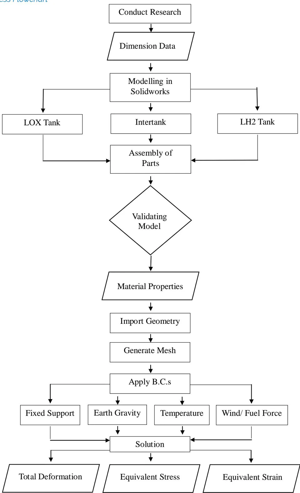
The flowchart above illustrates the procedural steps undertaken to obtain a solution. Gaining an understanding of the sequential progression of the process would be beneficial. The initial step is researching the external fuel tank of the launch vehicle. The dimensional data will be inputted throughout the modelling of the external fuel tank. The subsequent step involves modelling three components: the LOX tank, Intertank, and LH2 tank. The method of assembling all parts occurs next to the design phase. The model that has been constructed is subjected to a validation process to ascertain the level of perfection in its design. The subsequent procedure is conducted via Ansys software. The input of the material characteristics will be shown. The next step entails the importation of geometric data. Subsequently, the mesh will be generated. The next step involves the application of boundary conditions, including fixed support, the influence of earth gravity (weight), wind/fuel force, and air temperature/fuel temperature. The answer will be expressed in terms of total deformation, equivalent stress, and equivalent elastic strain. The above diagram illustrates the fundamental sequence of steps in the procedure. The prescribed flowchart conducts the analysis.
4.2 Model Development
4.2.1 External Fuel Tank of Launch Vehicle
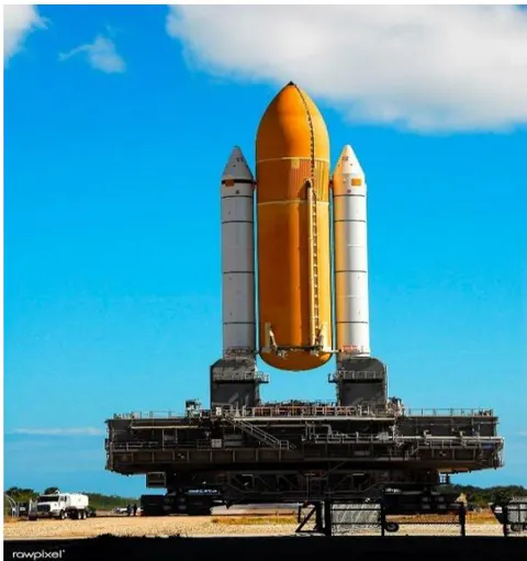
Launching the space shuttle into orbit necessitates a substantial quantity of fuel, exceeding 2 million litres, consumed during each launch. Additionally, a pretty voluminous tank is required to contain this fuel. The most significant and massive component of a fully fueled space shuttle is the externally mounted fuel tank, commonly referred to as an ET by the National Aeronautics and Space Administration. This tank has a rust-coloured appearance and possesses a bullet-like form.
The external tank, with dimensions of 46.9 metres in length and 8.4 metres in diameter, serves as the primary support structure for the shuttle during its launch phase. It is crucial in absorbing the substantial thrust of around 2.7 million kilograms created during the blast-off process. The primary function of the external tank, however, is to supply pressurised fuel to the three hydrogen-burning main engines of the shuttle during the eight-and-a-half-minute journey into space. The engines have a propellant consumption rate of 242,000 litres per minute.
{"image_source":{"path":"images/0839a328317168eadc21fbb8919823c19c0afde4d2e4b5388fdcbcbb9e0581eb.jpg"},"content":"","chart_caption":[{"type":"text","content":"Figure 2: Model of External Fuel Tank of Launch Vehicle"}],"chart_footnote":[]}
Transporting such a substantial amount of fuel into outer space presents considerable challenges. Specifically, almost one-quarter of the total launch weight of the shuttle, which amounts to 2 million kilograms (or 4.4 million pounds), is solely attributed to the importance of the fuel. However, contributing to the intricacy is the atypical composition of the power, which has only a distant resemblance to the petrochemicals commonly employed in the majority of motor vehicles.
The exterior tank is comprised of liquid hydrogen and liquid oxygen, which are extremely cold liquids that must be maintained at temperatures much below freezing, even in the typically warm climate prevalent in the Florida launch location of the shuttle. The external tank has many layers of specialised foam insulation to prevent ice formation on its outside surface in the hours before the launch. During the launch, ice present on the shuttle can detach and potentially cause harm to the spacecraft.
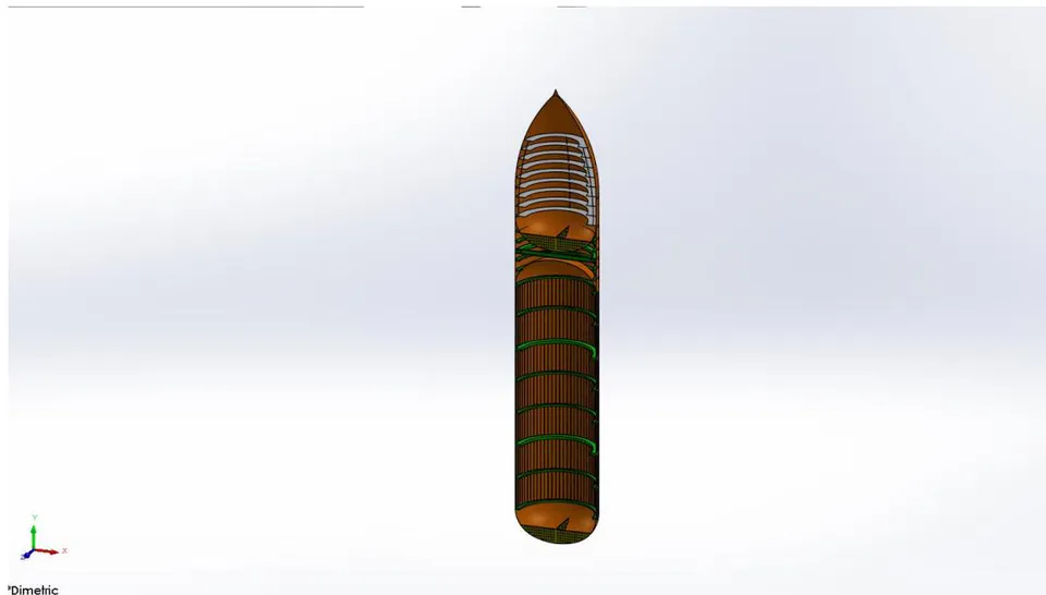
There are three main parts of the external fuel tank of the launch vehicle:
4.2.1.1 Liquid Oxygen Tank (LOX Tank)
Technical Specifications: [29]
Length = 16.6 m (16,600 mm)
Diameter = 8.4 m (8,400 mm)
Operation pressure: 34.7–36.7 psi (239–253 kPa) (absolute)
Thickness = 25 mm
{"image_source":{"path":"images/0f261be70ba34fcb12583d6c7c9d66231cad59945a19389e9b2edb62545f672c.jpg"},"content":"","chart_caption":[],"chart_footnote":[{"type":"text","content":"Figure 4: Liquid Oxygen Tank"}]} {"image_source":{"path":"images/0e5981bd129c4caaae2f051f2d76dd105eb53e2a5c966ffb4ab838524bc26516.jpg"},"content":"","chart_caption":[{"type":"text","content":"Figure 5: Sectional Diagram of Liquid Oxygen Tank"}],"chart_footnote":[]}
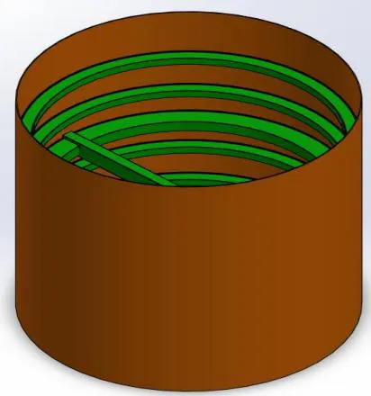
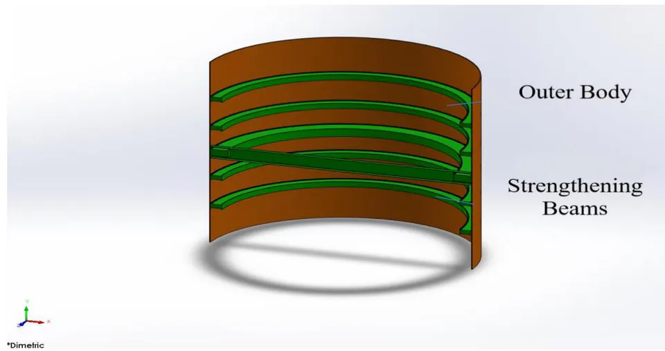
4.2.1.2 Intertank
Technical Specifications:
- Length: 22.6 ft (6,900 mm)
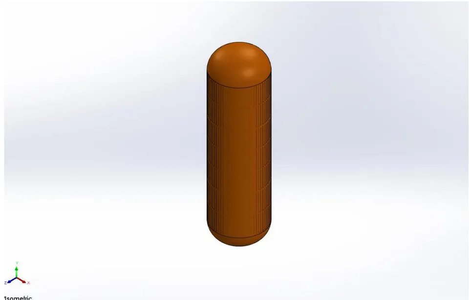
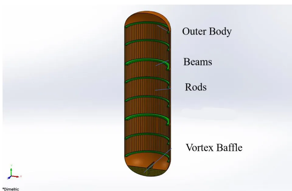
4.2.1.3 Liquid Hydrogen Tank (LH2 Tank)
Technical Specifications:
Length: 97.0 ft (29,600 mm)
Diameter: 27.6 ft (8,400 mm)
Operation pressure: 32–34 psi (220–230 kPa) (absolute)
Operation temperature: ( )
4.3 Material Properties
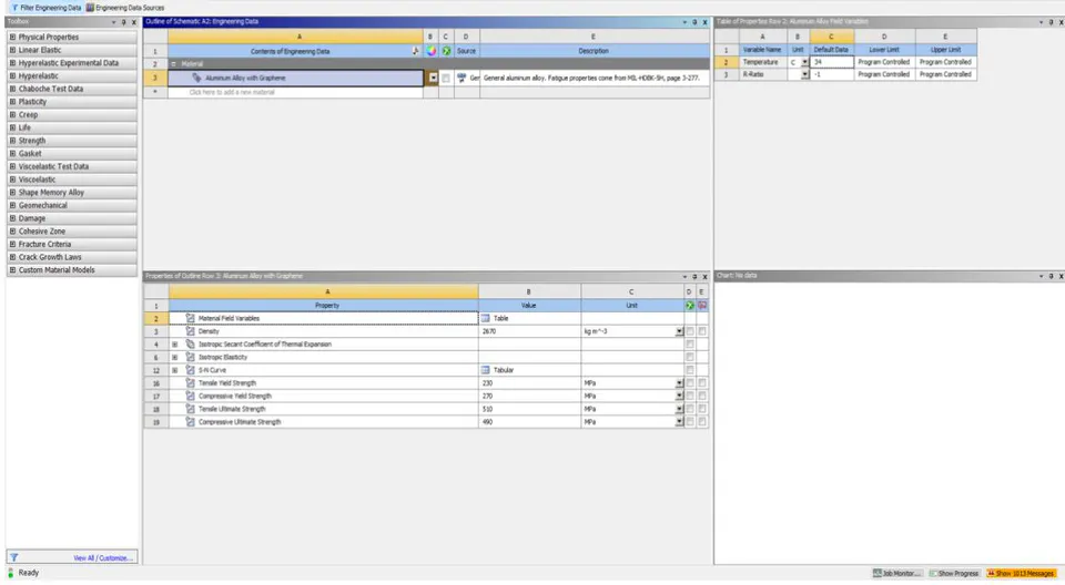
Material - 2195 Aluminium alloy with wt. Graphene
4.4 FEA on Composite Plate
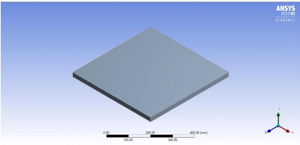
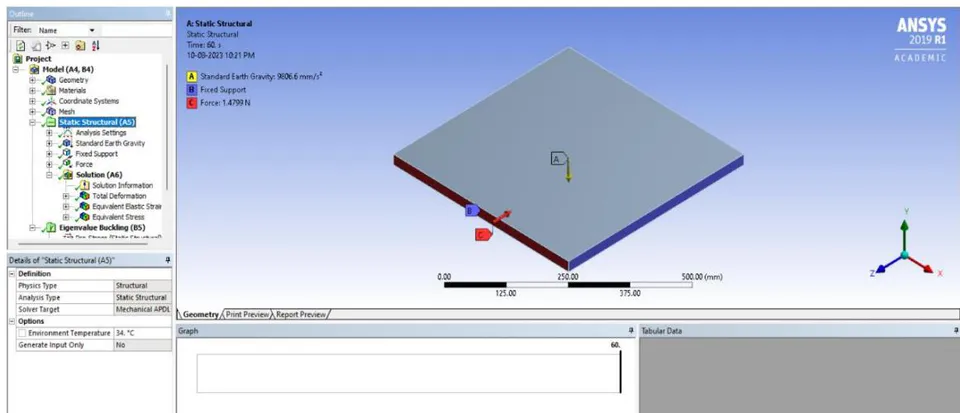
The static analysis is done on the 500x500x25 mm composite plate. There are several reasons to analyse composite plates.
Finite Element Analysis (FEA) is a computational method that enables the prediction of the structural response of a composite plate subjected to various loading circumstances, including mechanical loads, temperature variations, and external forces. Making accurate predictions is crucial in developing and optimising structures to ensure they perform their intended tasks effectively.
Conducting physical experiments on composite materials may be both time-consuming and costly. Finite Element Analysis (FEA) enables engineers to visually model various situations, saving time and cost by eliminating the need for repeated design iterations.
Finite Element Analysis (FEA) allows for optimising composite plate designs by examining different materials, geometries, and configuration combinations. This process determines the efficient and effective method of meeting the specified performance objectives.
Von Mises Stress:
The von Mises stress is a metric used to quantify the magnitude of the equivalent stress experienced by a material during plastic deformation. The significance of this phenomenon is in its ability to provide criteria for accurately anticipating the beginning of yielding or failure in materials that exhibit ductility. The von Mises stress is a measure considering the combined influence of everyday and shear stresses. It is often used in engineering contexts to evaluate various components' structural soundness and safety. The von Mises stress is very advantageous in scenarios characterised by the isotropic yield behaviour of a material, whereby the material's response to stress is consistent regardless of the particular orientation of the applied pressure. In plasticity theory and finite element analysis, it is customary to use a method to ascertain the critical stress thresholds at which plastic deformation occurs.
Von Mises Strain:
The Von Mises strain is a metric that quantifies a material's deformation or strain when subjected to external stress. The principle used is the von Mises yield criteria, which posits that a substance will undergo plastic deformation or yield whenever the von Mises stress is above a certain threshold. The von Mises strain is determined by evaluating the significant pressures, representing the highest and lowest strains encountered by the material along distinct orientations.
The von Mises strain is a scalar quantity that denotes the magnitude of pressure experienced by a material, considering the combined effect of many strain components. The measurement considers the cumulative impact of standard and shear stresses, assessing the material's total deformation. Structural analysis shows that this phenomenon proves advantageous when the material is exposed to intricate stress conditions.
It is used to evaluate the propensity for plastic deformation and failure of a material by using the von Mises strain calculation. The assessment aids in the determination of the structural integrity and dependability of construction when subjected to various loading scenarios.
Mesh:
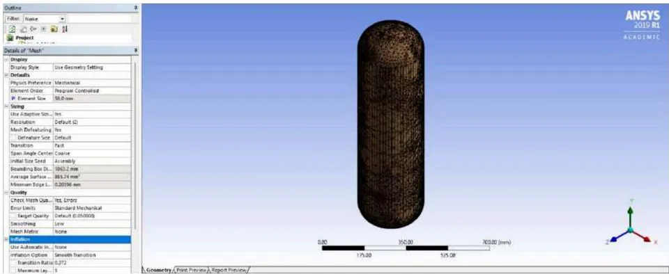
The mesh generation process has significant importance in finite element analysis (FEA) since it involves the division of the study continuum into discrete pieces or finite elements. The mesh functions as a discretised portrayal of the geometry, enabling the computation of approximate solutions to the governing equations. The mesh may be produced either manually or automatically. In manual meshing, the analyst generates the mesh by explicitly specifying the elements and nodes, considering the geometric characteristics and the desired degree of refinement. This methodology provides enhanced manipulation of the mesh quality and may be especially advantageous in accurately representing stress patterns at points of geometric discontinuity. In contrast, automated meshing entails using software tools to produce the mesh, using predetermined criteria such as element size, element type, and mesh density. This methodology exhibits enhanced speed and efficiency, mainly when dealing with intricate geometrical structures. Nevertheless, human meshing offers a higher degree of control compared to automated methods. The selection of mesh density or element size is paramount due to its impact on the analysis's precision and computing efficiency. Using a finer mesh in computer simulations yields more precise outcomes but costs more processing resources and time. Hence, it is common to strike a balance between precision and efficiency. In essence, mesh creation involves partitioning the analysis domain into discrete finite elements. The process may be executed manually or automatically, and the selection of mesh density plays a crucial role in attaining precise and effective outcomes in finite element analysis.
Applying loads and solution phase:
Applying Loads: Loads are essential in finite element analysis (FEA). It involves defining the external forces, pressures, displacements, or constraints that act on the model. These loads represent the real-world conditions the structure or component will experience during operation. The loads can be applied in various forms, such as point, distribution, pressure, thermal, or displacement constraints. The choice of load type depends on the specific analysis requirements and the behaviour of the structure under consideration. For example, point loads can represent concentrated forces or moments applied at particular locations in structural analysis. In contrast, distributed loads can represent uniform or varying loads applied over an area or along a line. Pressure loads can mean fluid or gas pressures acting on the surface of a structure, and thermal loads can represent temperature gradients or heat transfer effects. The loads should be applied in the same units as the specified model geometry and material properties. It is essential to accurately define the magnitude, direction, and location of the loads to obtain meaningful results from the analysis.
The solution phase in finite element analysis involves solving equations representing the model's behaviour under the applied loads. This is typically done using numerical methods and iterative algorithms. The solver takes the input from the pre-processor, including the mesh, material properties, and applied loads, and calculates the unknowns of the problem, such as displacements, stresses, strains, temperatures, or any other desired output. The solver uses the finite element method (FEM) to discretise the model into more minor elements and then assembles the element equations into a global system. These equations are then solved to obtain the solution for the unknowns. The solution process involves iterating through the equations until convergence is achieved, ensuring that the calculated values satisfy the equilibrium and compatibility conditions of the model. The convergence criteria are typically based on the desired accuracy and the convergence behaviour of the solution. Once the key is obtained, post-processing techniques are used to analyse and interpret the results. This may involve generating contour plots, deformed shapes, stress distributions, or other relevant visualisations to understand the model's behaviour under the applied loads.
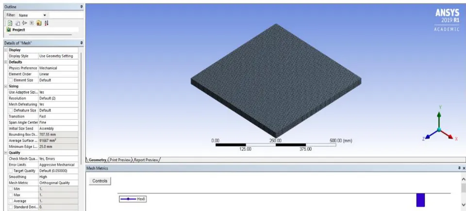
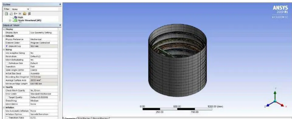
In order to obtain the most precise results, it is essential to maintain exact mesh settings. Mesh size is kept at 5 mm.
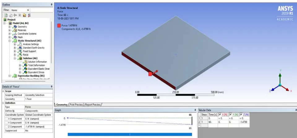
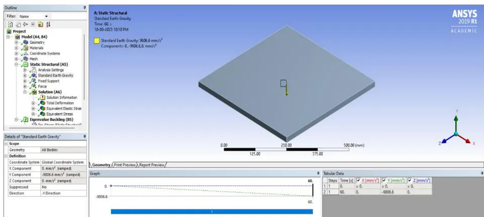
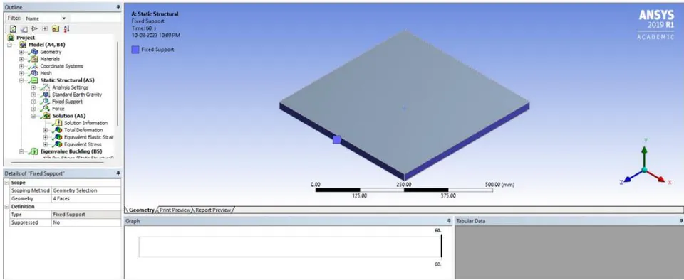
• Boundary Conditions for FEA Analysis
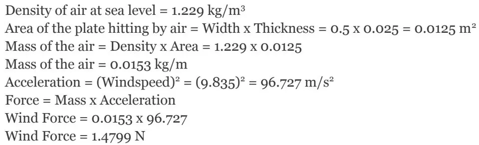
Wind Force Calculation
The launch can be considerably impacted by wind. The prevailing wind conditions on that particular day may influence the rocket's trajectory. Powerful gusts of wind can alter the missile'. The movement of wind exhibits variability in direction. However, in the launch context, it is advisable to conceptualise the wind as a horizontal vector perpendicular to the aircraft's vertical trajectory. In light of this circumstance, engaging in calculations and implementing model modifications is imperative to accommodate the disturbance.[35] For all the analysis, it is assumed that the launch will happen in Cornwall City, and wind will flow in the -Z Direction as the geometry is symmetric.
4.5 FEA on External Fuel Tank of Launch Vehicle
Finite Element Analysis (FEA) is pivotal in evaluating intricate systems' structural integrity and safety, such as launch vehicles and their accompanying external fuel tanks. The external fuel tank of a launch vehicle is of critical importance since it supplies the necessary propellant for the rocket's engines.
The launch vehicle's external fuel tank possesses a substantial propellant, rendering it a vital element of the launch vehicle. The structure must have the ability to endure the diverse range of loads and stresses encountered throughout different stages of the launch process, including liftoff, atmospheric pressures, and vibrations. Finite Element Analysis (FEA) is a valuable tool engineers use to effectively simulate and analyse the response of tanks to various loads. This process is crucial in ensuring the tank maintains its structural integrity and safety throughout its mission.
To optimise their payload capacity, launch vehicles must possess minimal weight. Finite Element Analysis (FEA) enables engineers to comprehensively examine various material selections, designs, and combinations to identify the most favourable equilibrium between structural integrity and weight. The optimisation process has the potential to provide substantial cost savings through the reduction of material requirements while ensuring the preservation of safety margins.
Finite Element Analysis (FEA) offers valuable insights into possible sources of failure inside the Electronic Funds Transfer (EFT) system. Engineers possess the capability to discern stress concentrations, places that are susceptible to buckling, and several other probable failure causes.
This information assists in the identification of design adjustments aimed at eliminating or mitigating these flaws before the launch, hence minimising the potential for catastrophic failure.
- Before constructing the external fuel tank, engineers can verify the soundness of their designs by employing Finite Element Analysis (FEA) simulations. The validation above method evaluates the tank's capacity to withstand the projected loads and stresses encountered during the launch. Identifying design problems early in development can prevent expensive redesigns and delays.
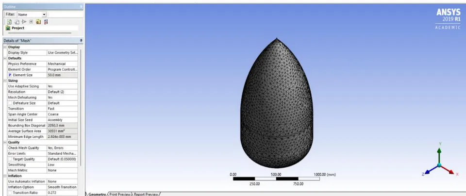
- Boundary Conditions for FEA Analysis
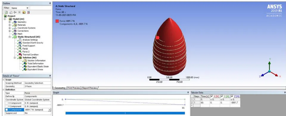
Wind Force Calculation
Highest Temperature in Cornwall = C
Wind Speed in Cornwall = 22 MPH = 9.835 m/s
Density of air at sea level = 1.229 kg/m
Area of the plate hitting by air = 747.9741 m
Mass of the air = Density x Area = 1.229 x 747.9741
Mass of the air = 919.26 kg/m
Acceleration = (Windspeed) = (9.835) = 96.727 m/s
Force = Mass x Acceleration
Wind Force = 919.26 x 96.727
Wind Force = 88916.79 N
Due to the RAM limitations and the massive size of the model, it has been scaled down by 1:10.
Wind Force = 88916.79/10
Wind Force = 8891.679 N
• Fuel Weight Calculation
The External Fuel Tank of the Space Shuttle is a prominent illustration. As per NASA's findings, the extraterrestrial entity was equipped with distinct chambers designated for storing liquid hydrogen and liquid oxygen fuel. The Space Shuttle's main engines utilised these propellants to create thrust during launch. Fuel combustion resulted in a notable reduction in the tank's weight, causing a displacement in the overall centre of mass of the entire assembly, including the orbiter, solid rocket boosters, and the external tank. This change's management was necessary to ensure the maintenance of steady flying.
In the initial phases of ascent, the launch vehicle encounters the highest magnitudes of aerodynamic forces and is subject to the influences of thrust and gravity. The thrust-to-weight ratio of a vehicle is influenced by the reduction in mass resulting from fuel consumption. A more excellent thrust-to-weight ratio facilitates enhanced acceleration of the vehicle. Engineers meticulously compute and optimise the ratio above to guarantee a secure and effective ascension.
Moreover, the weight of the gasoline impacts the structural factors that need to be considered for the tank. The tank must possess the necessary structural integrity to endure the forces generated by the residual fuel, both in the first stage of ascent and during the acceleration period. The alteration influences the tank's structural integrity in internal pressure resulting from gasoline use. Managing the dynamic pressure change is crucial to avert tank buckling or failure.
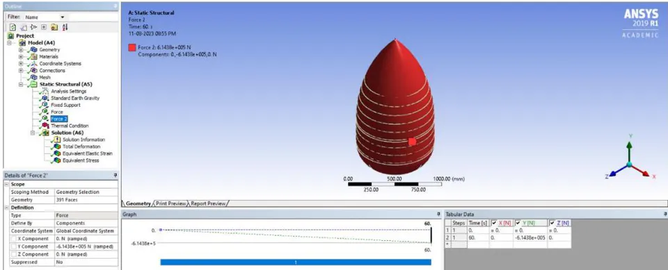
{"algorithm_caption":[],"algorithm_content":[{"type":"text","content":"The density of Liquid Oxygen = 1.141 kg/L = 1.141 g/mL "},{"type":"equation_inline","content":"^{[38]}"},{"type":"text","content":" \nAmount of Liquid Oxygen in Tank = 145000 Gallons "},{"type":"equation_inline","content":"^{[39]}"},{"type":"text","content":" \nKilograms = Gallons x 3.7854 x Density\nKilograms = 145000 x 3.7854 x 1.141\nFuel Force = 626277.45 N\nFuel Force = 626277.45/10\nFuel Force = 62627.745 N\nFuel temperature = -147.222 "},{"type":"equation_inline","content":"^{o}"}]}
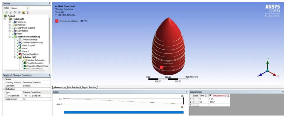
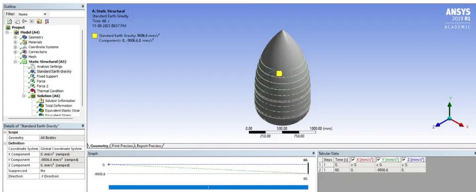
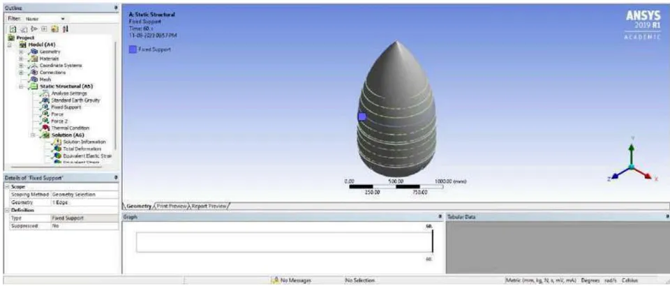
4.5.2 Intertank
• Boundary Conditions for FEA Analysis
Wind Force Calculation
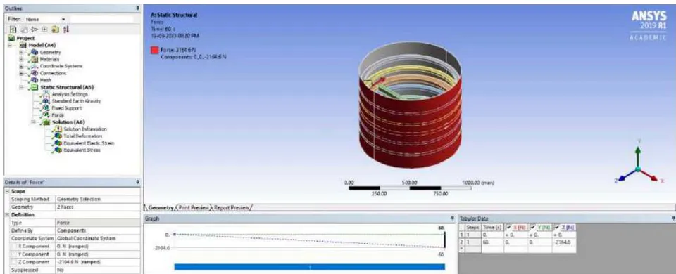
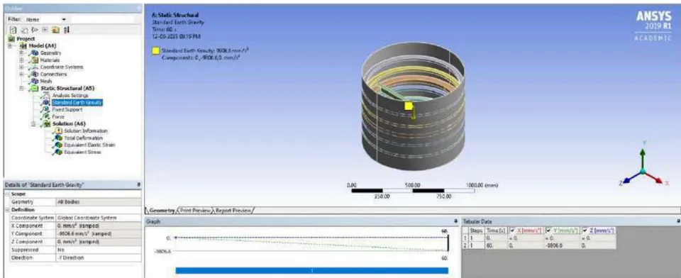
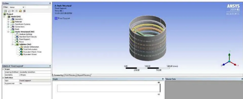
• Boundary Conditions for FEA Analysis
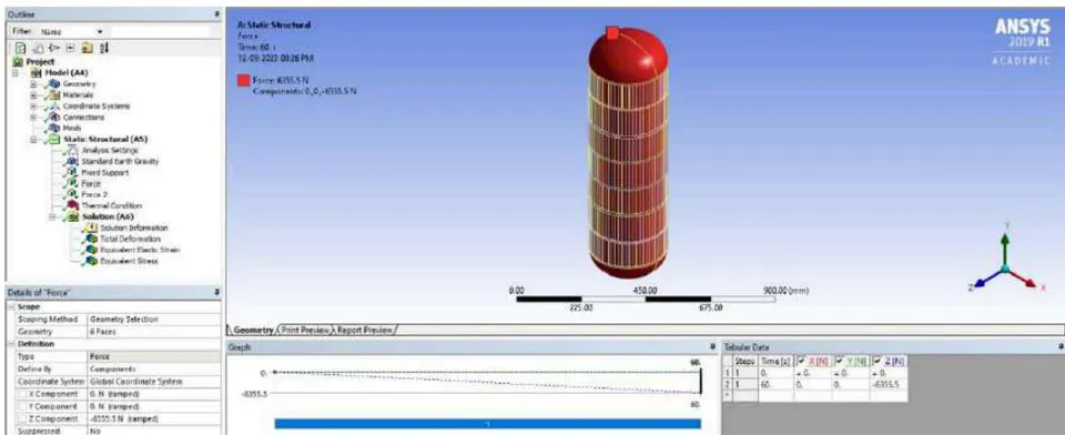
Wind Force Calculation
{"code_caption":[],"code_content":[{"type":"text","content":"Highest Temperature in Cornwall = 34°C\nWind Speed in Cornwall = 22 MPH = 9.835 m/s\nDensity of air at sea level = 1.229 kg/m3\nArea of the plate hitting by air = 1603.89 m2\nMass of the air = Density x Area = 1.229 x 1603.89\nMass of the air = 1971.18 kg/m\nAcceleration = (Windspeed)2 = (9.835)2 = 96.727 m/s2\nForce = Mass x Acceleration\nWind Force = 1971.18 x 96.727\nWind Force = 190666.41 N\nDue to the RAM limitations and the massive size of the model, it has been scaled down by 1:30.\nWind Force = 190666.41/30\nWind Force = 6355.547 N"}],"code_language":"txt"}
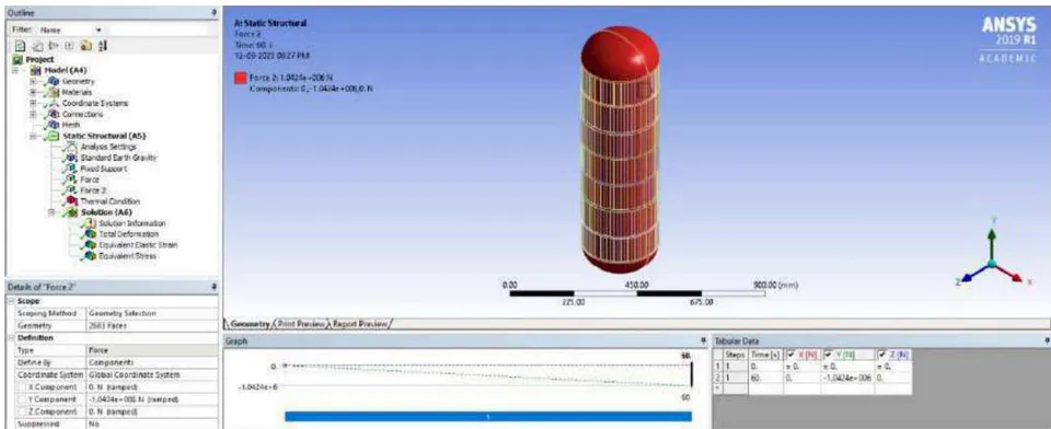
Fuel Weight Calculation
The density of Liquid Oxygen = 0.07085kg/L = 0.07085 g/mL
Amount of Liquid Oxygen in Tank = 390000 Gallons
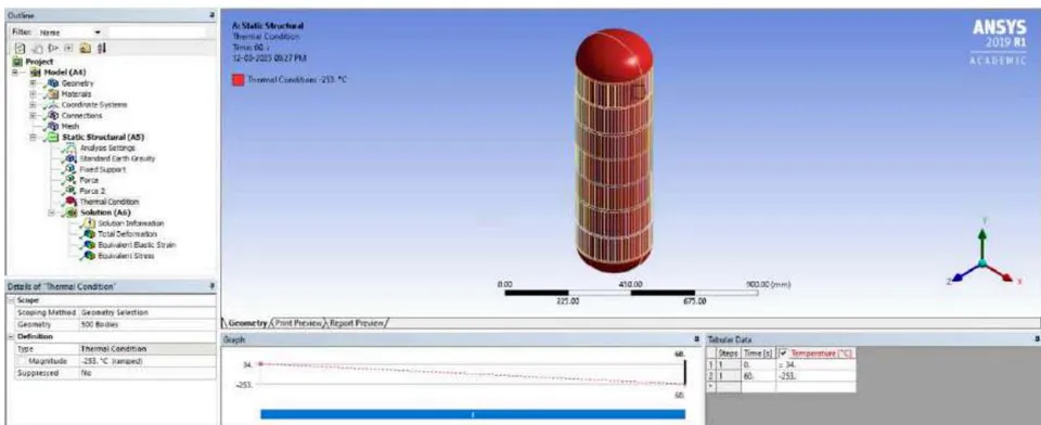
Kilograms = Gallons x 3.7854 x Density Kilograms = 390000 x 3.7854 x 0.07085 Fuel Force = 1042420.41 N Fuel Force = 1042420.41/30 Fuel Force = 34747.347 N Fuel temperature = -253°C
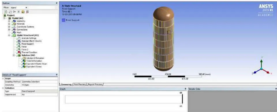
4.5.4 External Fuel Tank of Launch Vehicle
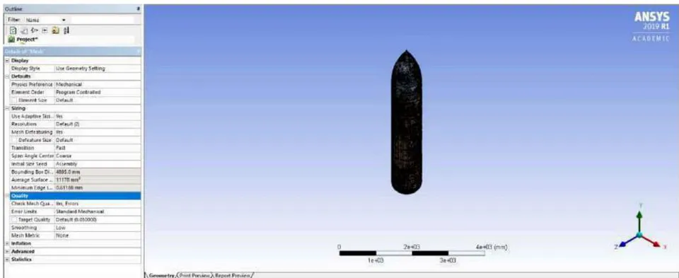
• Boundary Conditions for FEA Analysis
Wind Force Calculation
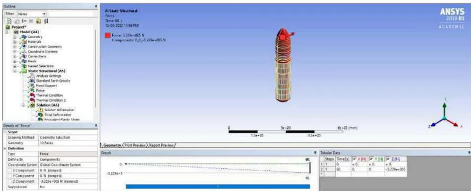
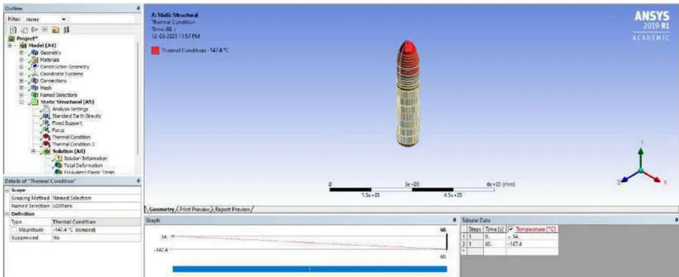
{"code_caption":[],"code_content":[{"type":"text","content":"It is assumed that the launch will happen in Cornwall City, and wind will flow in the -Z Direction as the geometry is symmetric.\n\nHighest Temperature in Cornwall = 34°C\n\nWind Speed in Cornwall = 22 MPH = 9.835 m/s\n\nDensity of air at sea level = 1.229 kg/m3\n\nArea of the plate hitting by air = 3872.0835 m2\n\nMass of the air = Density x Area = 1.229 x 3872.0835\n\nMass of the air = 4758.7906 kg/m\n\nAcceleration = (Windspeed)2 = (9.835)2 = 96.727 m/s2\n\nForce = Mass x Acceleration\n\nWind Force = 4758.7906 x 96.727\n\nWind Force = 331816.1937 N\n\nDue to the RAM limitations and the massive size of the model, it has been scaled down by 1:10.\n\nWind Force = 331816.1937/10\n\nWind Force = 33181.61937 N"}],"code_language":"txt"}
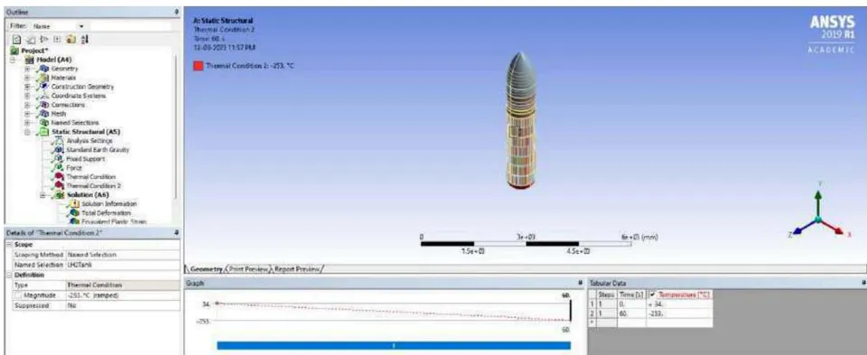
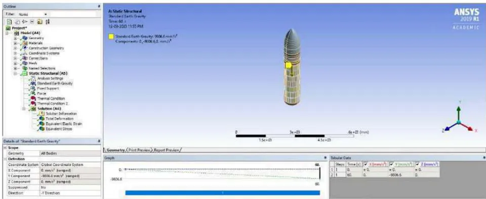
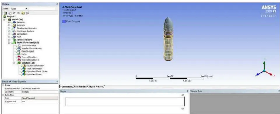
V. RESULTS
5.1 500x500x25 mm Plate
Deformation outcomes in ANSYS Workbench may often be represented as total or directed deformation. Both of these methods are used to derive displacements based on the analysis of stresses. In this particular instance, the overall distortion has been duly considered. The observed maximum deformation was 0.00051977 mm, indicating a very modest magnitude.
{"image_source":{"path":"images/8168e6d707d8839cf08758923521e1b237bb25ecd5a2152ded7570f32b2fc621.jpg"},"content":"","chart_caption":[{"type":"text","content":"Figure 39: 500x500x25 mm Plate's Total Deformation"}],"chart_footnote":[]} {"image_source":{"path":"images/3960ddca9dbf0a2778aebbe447d6861d2f833ecc842768798b70e4ea9d7e056c.jpg"},"content":"","chart_caption":[{"type":"text","content":"Figure 40: 500x500x25 mm Plate's Equivalent Stress"}],"chart_footnote":[]}
Figure 41 depicts the Equivalent elastic strain acting on the plate. The maximum strain that has been acting on the plate is .
{"image_source":{"path":"images/61dbc608b19b90deee41f026aa2bb819efe632af04017ee40afeab3dd0650fc0.jpg"},"content":"","chart_caption":[{"type":"text","content":"Figure 41: 500x500x25 mm Plate's Equivalent Elastic Strain"}],"chart_footnote":[]}
5.2 Liquid Oxygen Tank
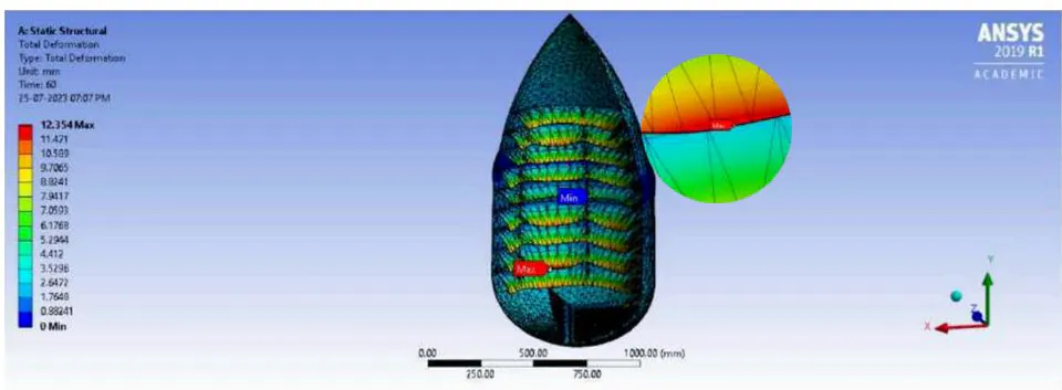
Figure 42 and Figure 43 represent the total deformation of the LOX Tank as well as a sectional view of the LOX Tank's total deformation, respectively. It was determined that the tank had a maximum distortion of 12.354 millimetres. The model is scaled down by 1:10, so the maximum deformation is 123.54 mm. In addition, the precise position of the highest deformation created is shown in Figure 43. Even if the degree of deformation is rather significant, fatigue is still possible with repeated use; this will need to be investigated.
{"image_source":{"path":"images/9393d42919234f8b2a6d27c466d434f0bab0b4922ae8764f6c66ab6f4807965a.jpg"},"content":"","chart_caption":[],"chart_footnote":[]}
Figures 44 and 45 show the equivalent stress on the LOX Tank. The maximum stress was found to be 14898.0 MPa. Although most of the tanks had equivalent stress between 1.9758 MPa and 1657.1 Mpa, there have been very few points on the LOX tank's surface where the stresses reached up to 14898.0 MPa. This will lead to the tank breaking as it exceeds the yield stress point.
{"image_source":{"path":"images/ae8f6f09e721bff4b372c7fcdc13b106176cda455b2428c14bb88429b15c4b4a.jpg"},"content":"","chart_caption":[],"chart_footnote":[]} {"image_source":{"path":"images/ac2d3ee7d540864f7dcfe575eb21dec4f909bea2fea69bd76e27fed57f910e60.jpg"},"content":"","chart_caption":[{"type":"text","content":"Figure 44: LOX Tank's Equivalent Stress"},{"type":"text","content":"Figure 45: Sectional View of LOX Tank's Equivalent Stress"}],"chart_footnote":[]}
Figures 46 and 47 show the Equivalent elastic strain of the fuel tank. The maximum strain on the fuel tank is found to be 0.21081.
{"image_source":{"path":"images/b0f74ac64f392132d644876441d81aa755d4514ae20e7cfbfe1073831cb00c44.jpg"},"content":"","chart_caption":[],"chart_footnote":[]} {"image_source":{"path":"images/df42be79dbb32a93a128b698e5f5ebd5a800de617743dbf1310ce0e466584538.jpg"},"content":"","chart_caption":[{"type":"text","content":"Figure 46: LOX Tank's Equivalent Elastic Strain"},{"type":"text","content":"Figure 47: Sectional View of LOX Tank's Equivalent Elastic Strain"}],"chart_footnote":[]}
5.3 Intertank
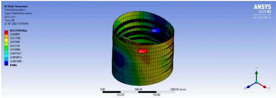
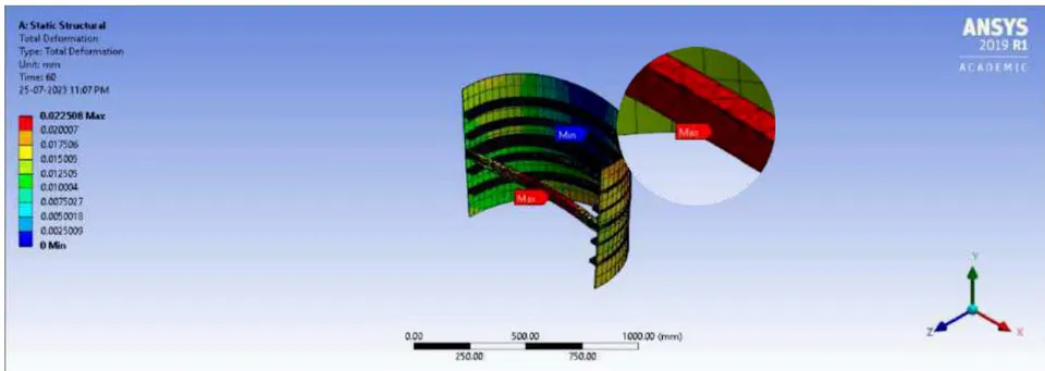
Figure 48 illustrates the total deformation of the Intertank, while Figure 49 presents a sectional view of the total deformation of the Intertank. The investigation revealed that the tank had a maximum deformation of 0.022 mm. The model is scaled down by 1:10. The maximum deformation is 0.22508 mm. Figure 49 depicts the precise spot where the most significant degree of deformation has been generated as an outcome of the loads acting. Despite the negligible magnitude of distortion, which may not need explicit acknowledgement, there is no possibility that prolonged use might result in fatigue.
Figures 50 and 51 depict the similar stress experienced by the Intertank. The investigation determined that the most significant stress observed was 31.246 MPa. The majority of the tank's surface exhibited deficient levels of stress. There is no potential for fatigue in this particular circumstance, unlike the scenario described in section 4.2.
{"image_source":{"path":"images/4b6a2183fadbf97980a25c4531fe60a53111476796cd63d0494ab88561cf30f6.jpg"},"content":"","chart_caption":[{"type":"text","content":"Figure 50: Intertank's Equivalent Stress"}],"chart_footnote":[]}
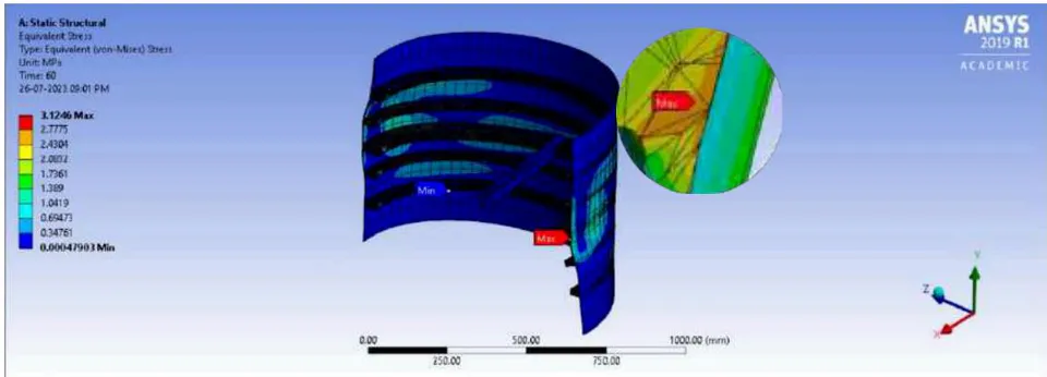
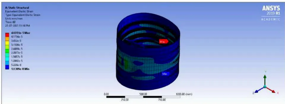
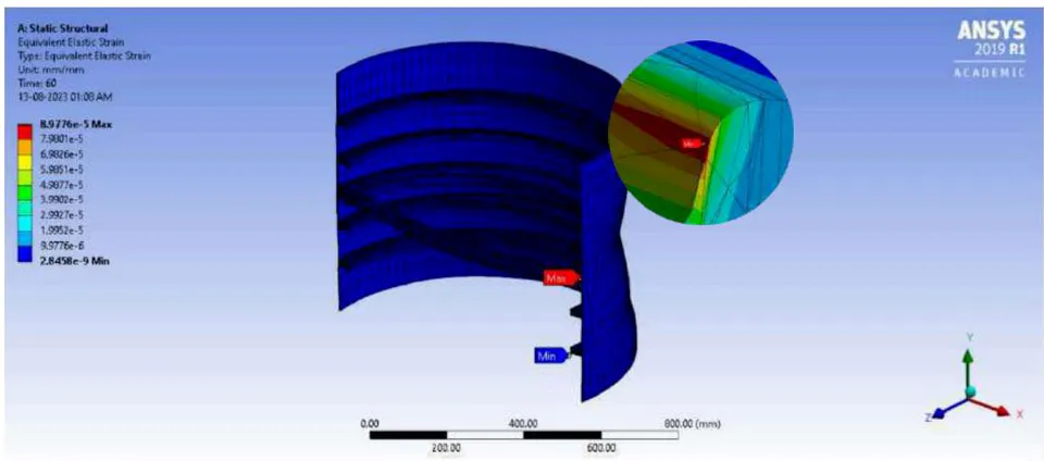
Figure 52 and 53 shows the Equivalent elastic strain of the fuel tank. The maximum strain on the fuel tank is found to be .
5.4 Liquid Hydrogen Tank
Figure 54 depicts the total deformation of the Liquid Hydrogen Tank, while Figure 55 provides a cross-sectional perspective of the overall deformation of the Liquid Hydrogen Tank. The examination findings indicated that the tank exhibited a maximum deformation of 3.6 mm. This model is scaled down by 1:30. Maximum deformation is 108 mm. Figure 55 illustrates the specific location where the most amount of deformation has been created as a result of the applied loads.
{"image_source":{"path":"images/21a1891b5481e6598ec1429870329ec307d190fdc62a6b3d52e12f3401ceb34c.jpg"},"content":"","chart_caption":[],"chart_footnote":[]} {"image_source":{"path":"images/deb34b6ffd16e5bf51f37f50ec0ecd488752226ae6264b8b775213bab64e4ccf.jpg"},"content":"","chart_caption":[{"type":"text","content":"Figure 54: LH2's Total Deformation"},{"type":"text","content":"Figure 55: Sectional View of LH2's Total Deformation"}],"chart_footnote":[]}
Figures 56 and 57 depict the equivalent stress experienced by the LH2 Tank. The experimental analysis yielded a maximum stress value of 2706.9 MPa. So, the model is scaled down by 1:30. Maximum stress is 81270 MPa.
{"image_source":{"path":"images/d195c74c379e456789c031be6c0d941787c542ec84ec65fccef4d26891ac2931.jpg"},"content":"","chart_caption":[{"type":"text","content":"Figure 56: LH2's Equivalent Stress"}],"chart_footnote":[]} {"image_source":{"path":"images/d9cecab53c991135ba7f84fb403308fb4ff7ae228411a3da043a1ea88627c541.jpg"},"content":"","chart_caption":[{"type":"text","content":"Figure 57: Sectional View of LH2's Equivalent Stress"}],"chart_footnote":[]}
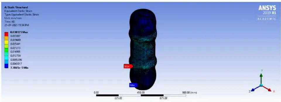
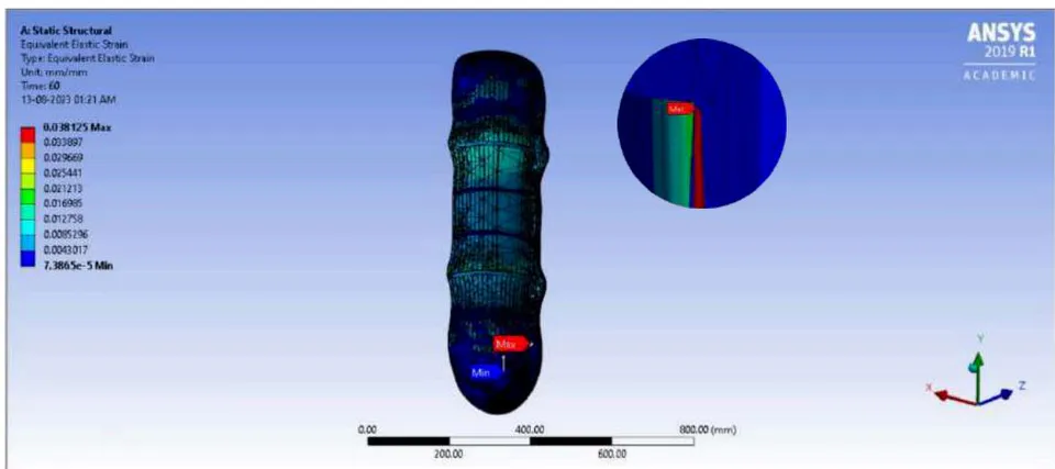
Figures 58 and 59 show the Equivalent elastic strain of the fuel tank. The maximum strain on the fuel tank is found to be 1.1437.
5.5 External Fuel Tank of Launch Vehicle
Figure 60 illustrates the total deformation of the External Fuel Tank, while Figure 55 presents a cross-sectional view of the total deformation of the External Fuel Tank. According to the results of the investigation, it was seen that the tank had a maximum distortion of 6.7 mm. However, the model is scaled down by 1:10. So the maximum deformation is 67.602 mm. Figure 49 depicts the precise place where the highest level of deformation has been generated due to the exerted loads. The potential for significant deformation is noteworthy, given the inherent risk of tank collapse.
{"image_source":{"path":"images/2dfe027514f4e91f8b298e669edd0160c5d28dcd4dcefe3981b325665c62e594.jpg"},"content":"","chart_caption":[{"type":"text","content":"Figure 60: EFT's Total Deformation"}],"chart_footnote":[]} {"image_source":{"path":"images/cad98b877de8dcb52260d3458ae29c3f41539f3379515f8701b35215fbd9870e.jpg"},"content":"","chart_caption":[{"type":"text","content":"Figure 61: Sectional View of EFT's Total Deformation"}],"chart_footnote":[]}
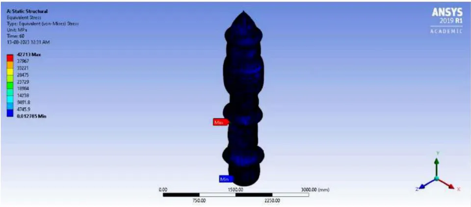
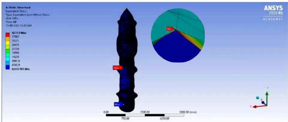
Figures 62 and 63 illustrate the equivalent stress encountered by the EF Tank. The experimental study resulted in a maximum stress value of 427130 MPa. The stress levels observed in the tank were mainly within the range of 0.128 MPa to 2000 MPa. However, a few particular spots on the surface of the EF tank revealed much higher stress values, reaching up to 427130 MPa. The tank's structural integrity will be compromised due to exceeding its yield stress limit.
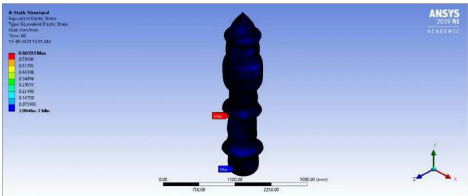
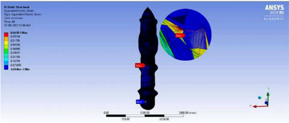
Figures 64 and 65 show the Equivalent elastic strain of the fuel tank. The maximum strain on the fuel tank is found to be 6.6593.
VI. CONCLUSION
To summarise, this report presents and discusses the findings of the deformation study conducted on many components of the launch vehicle, including the 500x500x25 mm plate, Liquid Oxygen (LOX) tank, Intertank, Liquid Hydrogen (LH2) tank, and External Fuel Tank (EFT). The study encompassed the assessment of total deformation, equivalent stress, and equivalent elastic strain for every component.
The 500x500x25 mm plate exhibited a maximum measured deformation of 0.00051977 mm, suggesting a relatively low level of distortion. The magnitude of the stress sustained by the plate was far below the yield strength h of the material. Concerns were raised over probable fatigue due to prolonged usage of the LOX tank since it exhibited a maximum deformation of 12.354 millimetres, a significant value warranting attention. The stress levels hit a crucial threshold beyond the material's yield stress, posing a tank failure risk.
In the case of the Intertank, it was seen that the most significant deformation experienced was measured to be 0.022 mm. The corresponding stress levels were relatively low, indicating a lower likelihood of encountering fatigue-induced problems. The LH2 tank demonstrated a notable maximum distortion of 3.6 mm, which, when extrapolated, amounted to 108 mm. The stress level of 2706.9 MPa is considerable, potentially jeopardising the tank's structural integrity.
A maximum deformation of 67.602 mm was found in the External Fuel Tank (EFT) instance. The stress equivalent exhibited localised regions with very elevated stress levels, potentially jeopardising the tank's integrity.
In general, several elements had minor distortions and stress levels below acceptable thresholds, while others gave rise to apprehension regarding possible fatigue and structural soundness concerns. The findings above underscore the significance of continuous inquiry and assessment to guarantee these components' safety and dependability throughout operating circumstances.
Conflict of Interest
The authors declare no conflict of interest.
Ethical Approval
Not applicable
Data Availability
The datasets used in this study are openly available at [repository link] and the source code is available on GitHub at [GitHub link].
Funding
This work did not receive any external funding.
References
Cite this article
Related Research


Special Issue
Launch a focused special issue to highlight research, emerging trends, and expert insights in your academic field.