



IntelliPaper
Abstract
With the advancement of the power battery and electric propulsion technology, the versatile redundancy enables the eVTOL aircraft design to be more reliable and cost-effective, thereby to be safer. This mandate the conducting of systematic aircraft level safety mitigation and comprehensive functional hazard assessment to ensure a fail-safe design, and process assurance to address the potential development errors in a pragmatic manner. After describing the application scenarios of eVTOL, the safety mitigation effects of applying
crashworthiness and ballistic rescue system (BRS) on eVTOL aircraft were analyzed and elaborated, and the flight profile of eVTOL was refined based on the aircraft level safety objectives. Utilizing the commercial aircraft system engineering approach, an aircraft level functional hierarchy was proposed for eVTOL, emphasizing completeness and correctness. Insight of the innovative features of the electric power battery system, the well-established aircraft functional hazard assessment (FHA) methodology was deployed to scrutinize the
functional inventory. Utilizing the conventional power battery system architecture found in Electric Vehicle (EV), the pertinent functions of the eVTOL's power battery system have been allocated in order to identify potential weaknesses and opportunities for improvement from a safety perspective in extant EV power battery systems. Suggestions were made after discussions that, prior to installing existing power battery systems into eVTOL aircraft applications, developers must not only enhance the availability, reliability, and safety of the battery system, but also identify and mitigate single-point failures and design errors within the extant battery system to substantiate the compliance to safety courses in airworthiness regulations.
Explore Digital Article Text
I. INTRODUCTION
As a novel component, the power battery system within electric Vertical TakeOff and Landing (eVTOL) aircraft introduces supplementary functionalities and components not found in traditional aircraft which is relying on fossil fuel-based power generation and distribution systems. Although the automobile functional safety is performed for Electric Vehicle (EV) power battery system, they do not align with the standards of aviation applications including eVTOL. The pressing concern within the eVTOL industry centers on establishing pragmatic and acceptable safety objectives for these systems and enhancing existing EV power battery systems to meet the safety requisites of eVTOL in a cost-effective manner.
To ensure the safe of flight for aircrafts, safety assessment methodology, system development processes, and SW/HW development standards have been established for commercial aviation . The Functional Hazard Assessment (FHA) is of fundamental importance in civil aviation industry, for both air transportation and general aviation including eVTOL aircraft. A systematic FHA also helps the designer to insightfully understand the functionality and safety risk at the very beginning, especially for the innovative portion of the aircraft, namely power battery system in eVTOL. It also contributes to the reasonable implementation fail-safe design and development assurance level definition.
II. AIRWORTHINESS CERTIFICATION REQUIREMENTS
Before industry development considerations in ARP 4754 (1996) [2], and even before System Safety Analysis and Assessment for Part 25 Airplanes in AC 25.1309-1 (1982) [3], the aviation industry utilized the function failure condition and severity to substantiate that "Catastrophic Failure Conditions must be Extremely Improbable" and "No single failure will result in a Catastrophic Failure Condition". The target and approach remain the same through the following decades, through the AC 25.1309-1A, AC 25.1309-1B arsenal draft, AC 20-174 and ARP 4754A [4]/ ARP 4761[5], and will remain in the same way for the next updated version ARP 4754B.
According to the latest airworthiness regulatory progress for eVTOL, the FHA is mandatory for design and development of eVTOL aircraft with and without occupants. Additional to the safety regulations applicable, the airworthiness criteria were defined for Model JAS4-1 Powered Lift, in which FAA proposes that compliance with the criteria will provide an equivalent level of safety to existing rules. The clause, JS4.2430, addresses the criteria for electric energy systems [6]:
2.1 Each Energy System Must
-
Be designed and arranged to provide independence between multiple energy-storage and supply systems, so that failure of any one component in one system will not result in loss of energy storage or supply of another system.
-
Be designed to prevent catastrophic events due to lightning strikes, taking into account direct and indirect effects on the aircraft where the exposure to lightning is likely.
The same safety assessment method, including FHA, is applicable to the UAS eVTOL that is closest to actual operation without pilot, namely EH216-S. For details, please refer to the clause numbered PEU.Fo10 (Systems, Equipment, and Installation) in the Special Conditions issued by the Civil Aviation Administration of China [7]:
-
Regarding the System, Equipment and Installation included in PEU.Foo(a), considered separately and in relation to other systems, must be designed so that -
-
The occurrence of any catastrophic failure condition is extremely improbable, and cannot be caused by a single point of failure.
The usage of Lithium-ion (Li-ion) batteries has increased significantly in recent years due to their long lifespan, high power density, and environmental benefits. However, various internal and external faults can occur during the battery operation, leading to performance issues and potentially serious consequences, such as thermal runaway, fires, or explosion . The battery management systems (BMS) has led international standards to demand functional safety in electro-mobility applications, with a special focus on electric vehicles . In , it provides a Guidance for Designing Safety into UAM and eVTOL, it suggests decomposing the function at the aircraft level with associated severity classification, then performs an FHA and a Systems Theoretic Process Analysis (STPA) on an eVTOL vehicle undergoing an UAM passenger carrying reference scenario. In , the System Functional Hazard Assessment (SFHA) on a specific unmanned aircraft according to the ATA sections is presented and identifies 311 hazards in which 108 cases were categorized as catastrophic.
The research from NASA describes the preliminary considerations for classifying hazards of unmanned aircraft systems. But very little of the research is specific to functionalities, failure conditions and classifications of eVTOL power battery systems neither the aircraft level safety mitigation approaches and effectiveness.
This manuscript comprehensively dissects the eVTOL's flight profile and delves into the impact of aircraft-level safety mitigation strategies. It proffers a meticulously constructed hierarchical framework for eVTOL's aircraft-level functionalities. Employing a rigorous and systematic approach, it conducts a detailed Functional Hazard Analysis (FHA) with a specific focus on the power battery system, thereby elucidating potential safety lacunae inherent in the incorporation of contemporary Electric Vehicle (EV) power battery systems into the eVTOL aircraft paradigm.
III. SAFETY OBJECTIVES OF EVTOL
From a safety standpoint, severity classification for aircraft level Failure Conditions (FC) is subject to the eVTOL ConOps (concept of operation), e.g. number of passengers, travel area, flight distance and altitude, etc., aircraft level safety mitigation and implementation, and the flight profile definitions, including flight phases definition. This necessitates the execution of a comprehensive analysis of application scenarios.
3.1 State of the Art for eVTOLConOps
Numerous eVTOL ConOps studies conducted by a range of entities, including Uber [13], the Federal Aviation Administration (FAA) [14], the European Union Aviation Safety Agency (EASA) [15], NASA [16], NUAIR [17], Wisk Aero & Skyport [18](Also known as vertiport), and others, have been published and ongoing updating. These studies have proposed business models, defined operational contexts, and outlined application scenarios with the aim of rendering urban air travel accessible to the general populace as a secure, economically viable, and pragmatic supplement and substitute for conventional modes of transportation. Almost all the application scenarios of eVTOL are targeted to Urban Air Mobility (UAM) operations, which makes better sense from business perspectives.
Besides the business aspects within all these descriptions of broad operational concepts, high-level functional capabilities and system requirements were also captured, which can be used to deduct the safety requirements for eVTOL.
Regarding for the eVTOL aircraft configuration, NASA practical concept vehicles [19] were designed with a range of potential aircraft types and propulsion system architectures, targeting at the UAM vision (six occupants at 1,200lb and 75 nm range), as illustrated in Fig. 1. These eVTOL configuration include:
-
Multirotor/quadrotor aircraft, with turboshaft and electric propulsion.
-
Side-by-side aircraft, with turboshaft and electric propulsion.
-
Lift and cruise aircraft with electric and turbo-electric propulsion.
-
Quiet single-main rotor helicopter with turboshaft and electric propulsion.
-
Tiltwing aircraft with turbo-electric propulsion.
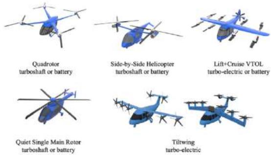 Fig. 1: Categorization of Emerging Electric Aircraft
3.2 Aircraft Level Safety Mitigation
Similar to the conventional general aviation aircraft development, meeting the safety standards mandated by certification regulations is paramount in bolstering safety measures for eVTOLs. Before delving into the safety impacts introduced by the power battery system and redundancy in propulsion, it is important to acknowledge the top-level safety mitigation effectiveness for the eVTOL aircraft configurations. What if the safety mitigations proven to be effective are deployed into an eVTOL aircraft? The following section clarified the effects of applying the crashworthiness mitigation and Ballistic Recovery Systems (BRS) in eVTOL aircraft.
3.2.1 Crashworthiness
According to 27.561 and 27.562 in the 14 FAR part 27 and part 29 for rotor wing general aviation, the aircraft should be tested to be safe for occupants at a velocity 30 ft/sec with a peak deceleration of 30 G's and occupants must be able to evacuate themselves after the impact. These certification clauses would be most likely applicable to vast majority of eVTOL, including multirotor, Lift Plus Cruise (LPC) and tilt wing VTOL aircraft configurations. As a proof to this point, the Crashworthiness Requirements Special Condition for VTOL from EASA demands the same test conditions.
Regarding to eVTOL aircraft, the vertical movement is quite stable at a very low speed, like a free fall test. This indicates the initial height of a rough free fall movement test of eVTOL crashworthiness should be no less than 10 meters, i.e. 32 ft above ground level (AGL) attitude. Before flying higher than this height, a thorough self-check would be performed to ensure the eVTOL is in a healthy condition and suitable for further operating. This altitude can be recognized as the decision point from safety perspective for eVTOL operation during takeoff, like the speed of V1 for making Rejected Take-Off (RTO) decision for transportation aircraft.
The effectiveness of crashworthiness is a sophisticated topic various from case to case. A study from NASA presented crashworthiness design mechanisms and the implementation within a six-passenger LPC eVTOL concept vehicle, which were evaluated under multi-axis dynamic loading conditions . The results of this study found the effectiveness of energy attenuating design mechanisms to be dependent on the complexity of load environment in which they were employed. An increase in off-axis loading resulted in a decrease in occupant protective capability.
3.2.2 Ballistic Rescue System
BRS is a parachute designed to be deployed in the event of an off-nominal condition for small aircraft. The BRS systems developed for Cirrus aircraft have been installed on numerous makes and models of aircraft . The successful deployment of the parachute within a BRS requires enough time for inflation the canopy with minimum vertical height and/or horizontal speed as presented in Fig. 2. According to the installation and user guide from BRS suppliers [22][23], the minimum firing height of 100 ft (30 m) for canopy without slider (measured at 38mph (60km/h) in horizontal flight) and 200 ft (60 m) for canopy with slider, may not always be a safe height from which to fire the system. The eVOTL aircraft is a complex design requiring integrity of the structure, indicating the parachute with slider takes preference. It would be the common choice for a BRS with slider from safety and customers experiences perspective.
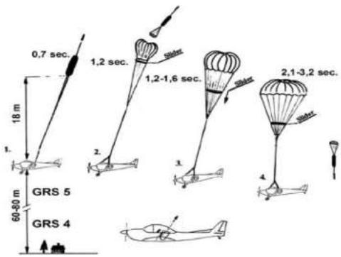 Fig. 2: Successful Deployment of BRS Parachute
In summary, the manuscript suggests a minimum firing height of 200-250 ft (60–76 m) for eVTOL BRS. Since the eVTOL aircraft is usually heavier and slower than a typical light sport aircraft (LSA) application, 250 ft (76m) should be the recommended altitude of BRS application. The BRS provides some deceleration stress even below the minimal height, it would be of 10% efficiency under 150 ft and 50% efficiency between 150 ft and 250 ft. The also provide the protection against crash and can lower the catastrophic severity to hazardous.
3.2.3 eVTOL Flight Profile Refinement
Although the flight profile was demonstrated in the Con Ops as part of the application scenario, further clarification and refinement of quantitative parameters are needed after an effectiveness analysis from a safety perspective regarding crashworthiness and the application of Ballistic Rescue Systems (BRS), before the failure conditions assessment for each of the function.
Based on the scrutiny of crashworthiness and BRS, the altitude above ground scales in the eVTOL flight envelop can be further clarified as following:
-
The is the minimal altitude of BRS full effective usage, i.e. 250 ft (76m) AGL; eVTOL would cruise above this altitude.
-
The serves as an indicator of diminished BRS efficacy. Within the span of 150 feet (45 meters) to 250 feet (76 meters), the effectiveness of BRS protection experiences attenuation, during which the degree of severity can be alleviated to a lower threshold through the utilization of the BRS.
-
The indicates the safe area and altitude provided by the vertiport safety mitigation during the takeoff and landing periods of the eVTOL operation.
-
The is the safe altitude of crashworthiness, namely 32 ft (10m) AGL, indicated and derived from the crashworthiness regulations. It's also the maximum altitude for performing the health check during the takeoff.
-
Currently, there's no effective mitigation approach from occupant safety point of view at the height between 32 ft and 150 ft.
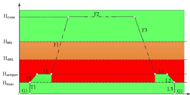
Fig. 3: eVTOL flight profile with safety mitigation Fig. 3: eVTOL flight profile with safety mitigation By aligning the Uber flight profile to the see VTOL altitude definitions, Fig. 3 shows the severity classification for the flight of an eVTOL with the BRS and crashworthiness mitigation designs. After aircraft level safety mitigations, the red area means no effective means to control and complement the safety impacts when failure happens, which also concludes that the top-level safety objective for eVTOL aircraft is catastrophic. The notional flight phase definition for eVTOL aircraft based on the refined flight profile and safety consideration is presented in the following table:
Table I: Flight Phase Definition for UAM Note: the collision and avoidance during flight related to ATM (Air Traffic Management) was not considered in this paper since it more focused on the battery management system additional to the traditional fossil energy aircraft.
| Seg | Flight phase | Safety consideration |
| G1 | Ground Taxi | no safety impacts |
| T1 | Hover climb | Crashworthiness implementation |
| T2 | Transition +climb | Ground facilities(e.g. Vertiport) ensure the departure safety |
| T3 | Departure terminal procedure | Ground facilities(e.g. Vertiport) provide the departure safety mitigation (to ensure the $H_{hover}$ is satisfied during the departure phase) |
| F1 | Accelerate+ climb | No safety mitigation under 150 ft which could lead to catastrophic, half efficiency at 150 ft & 250ft |
| F2 | Cruise | BRS provides safety mitigation |
| F3 | Decelerate + descend | No safety mitigation under 150 ft which could lead to catastrophic, half efficiency at 150 ft & 250ft |
| L1 | Arrival terminal procedure | Ground facilities (e.g. Vertiport) provide the arrival safety mitigation |
| L2 | Transition + descend | Ground facilities (e.g. Vertiport) provide the arrival safety mitigation |
| L3 | Hover descend | Crashworthiness implementation |
| G1 | Ground taxi | no safety impacts |
IV. AIRCRAFT LEVEL FHA
At the aircraft level, the FHA examines comprehensively how the function can fail without regards to any specific implementation and/or interface.
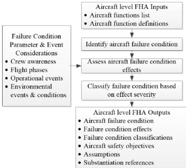 Fig. 4: AHF activities
In the realm of civil aircraft and system development, Aircraft level HFA is performed early in the development process, and to be reevaluated anytime significant changes are made to aircraft functionality. It is used to establish the safety objectives for the functions of the aircraft to achieve a safe design. The FHA process is a top-down method for examining the function list and flight phases definition, identifying failure conditions and assessing the severity of failure condition effects. A typical FHA work process is shown in Fig. 4 The assessment process consists of the following activities:
-
Gather aircraft level FHA inputs.
-
Review and confirm the aircraft level functions are complete.
-
Determine the failure conditions associated with the aircraft functions.
-
Determine the effects of each failure condition considering flight phases (elaborated in Table 1), operational and environmental conditions and events, and crew awareness.
-
Assess and classify the severity of each failure condition's effects.
-
Capture and confirm aircraft level FHA assumptions.
When performing the aircraft level FHA, failure conditions are analyzed for their effect on the aircraft, crew and occupants to determine the associated severity classification. Flight phase, environmental and operational conditions should be also considered during the assessment.
3.1 Aircraft Level function list
The aircraft level FHA commences with a function list at aircraft level. Much discussion has focused on how to define an appropriate list of aircraft functions for UAM. Difficulties stem from aircraft novelty, new kinds of automation, and misunderstanding of function lists. A function list focuses on what a thing (aircraft or system) must do, not what it has. This is because you cannot know how a thing may fail unless you know what it is supposed to do.
It is recognized that there is considerable variation among eVTOL aircrafts. However, a core set of functionalities that most aircraft will need to operate routinely and safely within the national airspace system are identified based on the industry standards and latest research from:
★ Conventional function definition for commercial aircraft based on the Specification for Manufacturers' Technical Data published by Air Transport Association (ATA) [26],
★ Function definition for traditional Unmanned Aircraft Systems with power battery system [27],
★ Reference studies for innovative features and relevant functions dedicated to eVTOL [28].
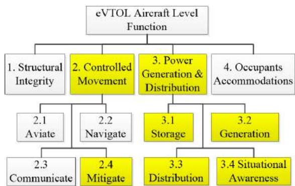 Fig. 5: eVTOL Function Decomposition at Aircraft Level
The functionality hierarchy presented herein is one of the many possible valid hierarchies. At the eVTOL aircraft level, the functionality includes providing:
1) Structural integrity.
2) Controlled movement.
3) Power generation and distribution.
4) Occupants' accommodations.
The aircraft level functions will be further broken-down into the next level as shown in Fig. 5. The "new" functionality introduced, or conventional functions impacted by the electric features of an eVTOL are highlighted in yellow in the diagram.
The core set of functions of "controlled movement" is to address the fundamental tenets of piloting; namely, to fly the plane (aviate), fly it in the right direction (navigate), and to state your condition or intentions to people inside and outside the vehicle (communicate). Finally, regarding for the operational concept of eVTOL, e.g. air mobility traffic management, detect and avoidance and the simplified vehicle operations (SVO) with artificial intelligence supports, as well as the aircraft level safety mitigation design, a fourth fundamental function was added as mitigate (as in mitigation of hazards). This function is intended to capture those actions necessary to (1)mitigate the occupant's safety by crashworthiness design and BRS design;(2) detection and avoidance; (3) provide SVO with artificial intelligence supports; (4) manage contingency situations that may arise.
Under the branch of "power generation and distribution" function, the decomposition is based on the combination of the functional definitions for Electric Vehicle power system and conventional aircraft power system function definition. The aircraft level power battery system functionality consists of:
- Storage of electric power, including battery pack for power storage; power storage interfaces, e.g. interfaces for battery charge and discharge; high-voltage protection interface against current leakage; structural protection for battery cell isolation and structural damage.
Generation of electric power, including the interface for transferring the electric energy to power battery storage, balancing power storage among battery cells, and protection against current leakage during the charging phase.
-
Electric power distribution provides power to the movement functions (i.e. propulsion, lift and control etc.), power discharge, balancing and protection.
-
Situational awareness provides flight crews and passengers with the indication and announcement relevant to electric power supply for normal flight operation and safety mitigation and provides the thermal management and maintains the battery health and capacity status.
The breakdowns of the functions of "provide controlled movement" and "provide power generation and distribution" are shown in the following Fig. 6 and Fig. 7.
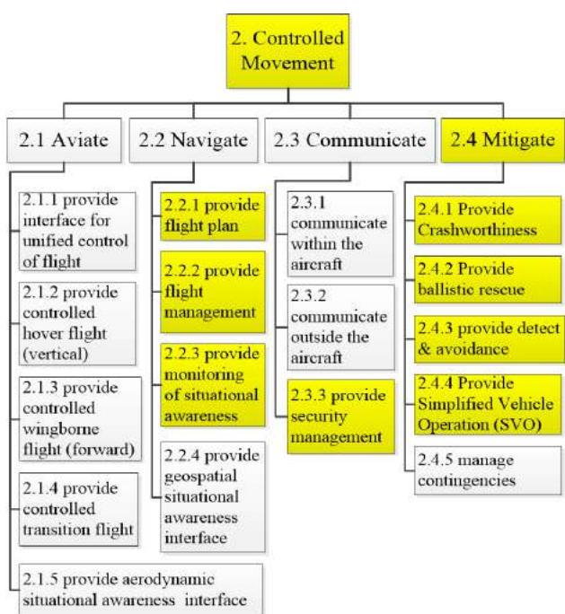
Fig. 6: eVTOL Function Decomposition for "Controlled Movement"
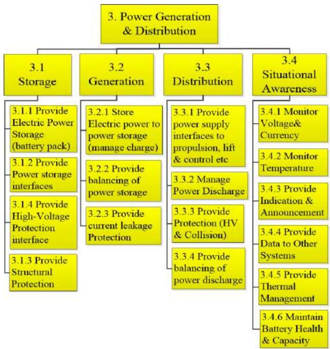 Fig. 7: eVTOL Function Decomposition for "Power Generation & Distribution"
4.2 aircraft level failure conditions
Failure conditions describe a failed state of the aircraft function including the amount and type of impairment. Knowledge of each function is necessary to properly define failure conditions which are correct in the context of the aircraft function, operation, and environment. Failure conditions in the FHA are broadly stated to provide a scope which encompasses all detailed failure scenarios that can lead to the top-level functional effect.
A failure condition is described by a statement that characterizes an abnormal state of a function. Failure conditions can be broadly categorized as the loss of a function or as a malfunction. Each function should be assessed and the potential for loss of the function and malfunction considered. In general, each aircraft function will have at least one loss of function and one malfunction of interest. Basic categories of function failure include:
4.2.1 Loss of the Function
Loss of function may be total or partial. Total loss of function is a condition where the function cannot be performed by any means. Partial losses of function are conditions where the function can still be performed but only at reduced effectiveness, with increased difficulty or by means other than the normal means used to accomplish it.
4.2.2 Malfunction
Malfunction is a condition where the operation of a function is different than intended excluding function loss. The aspect of the function which is incorrectly performed is described in the failure condition (e. g., erroneous, un-commanded/inadvertent action, misleading).
As an example of the deployment of the function failure condition analysis, the failure condition for the innovative eVTOL functions under "Provide Communication" are listed in the following table.
Table 2: Aircraft Level Function Failure Condition Matrix (Example)
| ID# | Aircraft Function | Total loss | Partial loss | Mal-function |
| 2 Provide Controlled Movement | ||||
| 2.3 Provide Communication | ||||
| 2.3.1 | Provide Security Management | 2.3.1. TL Loss of the ability for security protection | 2.3.1. PL Partial loss of the ability for security protection | 2.3.1. MF1 Overprotection or mistakes during security protection |
| 2.4 Provide Mitigation of Hazards | ||||
| 2.4.1 | Provide Crashworthiness | 2.4.1. TL Loss of the ability for occupant protect | 2.4.1. PL Partial Loss of the ability for occupant protect | NA |
| 2.4.2 | Provide Ballistic Recue | 2.4.1. TL Loss of the ability for occupant protect | 2.4.1. PL Partial Loss of the ability for occupant protect | 2.4.1. MF1 un-commanded deployment of parachute 2.4.1. MF2 fail to deploy parachute (contribute to Loss) |
| 2.4.3 | Provide detect and avoidance | 2.4.3. TL Loss of the ability for detection and avoidance | 2.4.3. TL Partial Loss of the ability for detection and avoidance | 2.4.3. MF1 fail to detect & report dangers. 2.4.3. MF2 report dangers by mistake |
| 3 Provide Power Generation & Distribution | ||||
| 3.1 Provide Power Storage | ||||
| 3.2 Provide Power Generation | ||||
| 3.3 Provide Power Distribution | ||||
| 3.4 Provide Situational Awareness | ||||
The same approach applies to the "Power Generation & Distribution" function, and the relevant failure conditions identified under total loss, partial loss and malfunction are summarized as following:
-
Total loss
-
3.1. TL1 Total loss of power
-
3.2. TL Thermal runaway
-
3.1. TL2 Current leakage
-
3.4. TL Total loss of power information
-
Partial loss
-
3.1. PL Asymmetric loss of power
-
3.2. PL Thermal runaway
-
3.3. PL Current leakage
-
3.4. PL Partial loss of power information
-
Malfunction
-
3.3. MF1 Inadvertent power off
-
3.3. MF2 Un-commended power supply
-
3.2. MF1 Current leakage
-
3.2. MF2 Thermal runaway
-
3.4. MF1 Erroneous power supply information without announcement to the flight crew
4.3 Aircraft Level FHA
The effects are captured based on their immediate effect on aircraft, flight crew and occupants during the phase of flight being analyzed. The qualitative classification of the failure conditions is listed in the following table 3.
Table 3: Failure Condition Classifications of eVTOL
| Class | Aircraft | Crew | Occupants |
| CAT | Normally with hull loss | Fatal injury or incapacitation | Multiple fatalities |
| HAZ | Large reduction in functional capabilities or safety margins | Physical distress or excessive workload impairs ability to perform tasks | Serious or fatal injury to an occupant |
| MAJ | Significant reduction in functional capabilities or safety margins | Physical discomfort or a significant increase in workload | Physical distress to passengers, possibly including injuries |
| MIN | Slight reduction in functional capabilities or safety margins | Slight increase in workload or use of emergency procedures | No effect on flight crew |
| No-Effect | Inconvenience for passengers | No effect on flight crew | No effect on operational capabilities or safety |
The allowable quantitative probability requirement for each of the classification are identified in the ASTM document (F3230-17 [30], Table 5). The quantitative objective for each classification is listed as following:
★ CAT (Catastrophic),<10 per flight hour;
★ HAZ (Hazardous),<10 per flight hour;
★ MAJ (Major),<10 per flight hour;
★ MIN (Minor),<10 per flight hour;
★ No-Effect, No Probability Requirement
It is recognized that when designing civil aircraft systems, the manufacturers should prevent any single failure that leads to a catastrophic failure condition in air transportation, General Aviation and eVTOL aircraft.
The detailed aircraft level FHA for battery system is in Table 4.
Table 4: Aircraft FHA for Electric Power Generation & Production
| FC. No. | FC Description | Flight Phase | Effect of FC on: A. Aircraft B. Crew C. Occupants | FC Class. | Remarks/Justification |
| 3.1.TL1 | Total loss of power | F1, F3 | A. Airplane unable to provide continued safe flight along desired flight path. Airplane impact with ground or surroundings resulting in significant airplane damage or hull loss.B. Flight crew unable to maintain desired flight path. Flight Crew fatalities.C. Passenger fatalities. | CAT | During the flight phase of F1 and F3 between the $H_{hover}$ and $H_{rBRS}$ , BRS and crashworthiness cannot provide effective safety mitigations |
| 3.2.TL3.2.PL3.2.ML2 | Thermal runaway | all phase | A. Aircraft burst into fire. Airplane unable to provide continued safe operation. Airplane impact with ground or surroundings resulting insignificant airplane damage or hull loss.B. Flight crew unable to control aircraft. Flight Crew fatalities.C. Passenger fatalities. | CAT | Battery thermal runaway causes fire or even explosion at any flight phase, leaving little time to respond |
| 3.1.TL23.2.PL3.2.ML1 | Current leakage of high-voltage battery | all phase | A. Airplane unable to provide operation. Large reduction in safety margin.B. Crew experiences excessive workload to control direction resulting inability to perform required tasks.C. Potential injury or death to some of the passengers. | CAT | Current leakage from high-voltage causes crew to lose consciousness |
| 3.4.TL3.4.PL | Total loss of power information | T1, T2, T3, F1, F3, L1, L2,L3 | A. Airplane unable to provide power information. Large reduction in safety margin.B. Crew experiences excessive workload to compensate.C. No effect | MAJ | Trigger emergency landing procedure when crew identify the total loss of power information |
| 3.1.PL | Asymmetric loss of power (partial loss) | T2, T3, F1, F3, L1, L2 | A. Airplane unable to provide continued safe flight along desired flight path. Airplane impact with ground or surroundings resulting in significant airplane damage or hull loss.B. Flight crew unable to maintain desired flight path. Flight Crew fatalities.C. Passenger fatalities. | CAT | |
| 3.3.ML1 | Inadvertent power off | F1, F3 | A. Airplane unable to provide continued safe flight along desired flight path. Airplane impact with ground or surroundings resulting in significant airplane damage or hull loss.B. Flight crew unable to maintain desired flight path. Flight Crew fatalities. | CAT | |
| C. Passenger fatalities. | |||||
| 3.3.ML2 | Un-commended/uncontrolled power supply | T2, T3, F1, F3, L1, L2 | A. Airplane unstable along desired flight path. Excessive power supply causes unstable flight.B. Pilot able to maintain control using reduce electric motor rpms on failed wingtip. Pilot adjusts lift on other rotors for immediate landing.C. Passenger experience discomfort | HAZ | Assumption: that this level of manual control is available to the pilot, and they are sufficiently trained to detect and respond to this hazard. |
| 3.4.ML1 | Erroneous power supply information without announcement to the flight crew | T2, T3, F1, F3, L1, L2 | A. Airplane unable to provide continued safe flight along desired flight path. Airplane impact with ground or surroundings resulting in significant airplane damage or hull loss.B. Flight crew unable to maintain desired flight path. Flight Crew fatalities.C. Passenger fatalities. | CAT | Misleading to the flight crew |
The function of electric power storage, generation, distribution and situational awareness functions under "power generation and distribution" are identified to be of CAT class according to the failure conditions, including:
-
Total loss of power when flying across the height of without effective BRS and crashworthiness mitigations.
-
Thermal runaway through all flight phases (even on ground) especially without warning information as undetected failures.
-
Current leakage of high-voltage battery causes crew to lose consciousness.
-
Asymmetric loss of power causes uncontrollable movements due to partial loss of power supply.
-
Inadvertent power off during flight due to un-commended action or data error on the data bus;
6) Erroneous power supply information without announcement to the flight crew (misleading)
3.4 Allocate Aircraft Functions to Systems
The system architecture establishes the structure and boundaries within which specific item designs are implemented to meet the functional requirements and safety objectives. More than one candidate system architecture may be considered for implementation. These candidate system architectures may be evaluated using such factors as technology readiness, implementation schedules, producibility, contractual obligations, economics, prior experience and industry precedence. Aiming to a LPC eVTOL configuration and architecture, the function allocation is conducted as shown in Fig.
The highlighted boxes in yellow are those impacted by the innovative feature, power battery system.
★ The power storage, generation, distribution and situational awareness function are allocated to the "aircraft battery system" and "flight and propulsion control electronics".
★ The innovative functionality of eVTOL, including SVO and security protection, is implemented by flight deck and annunciations/function controls as hosted applications.
★ Detection & avoidance, BRS and crashworthiness protection are allocated to standalone systems additional to traditional GA avionics system.
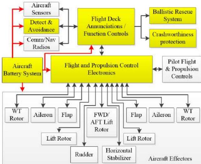 Fig. 8: eVTOL Aircraft Level Architecture
During the function allocation process, the independence among systems should be considered to ensure a fail-safe design. The fail-safe concept and techniques are discussed in the AMJ/AC 25.1309-1A to support this approach. ASTM F3230 [30] section 4.2.4.3 prescribes that "no catastrophic failure condition should result from failure of a single component, part or element of a system." Even for eVTOL, the common-mode failure analysis should be performed to ensure that failures of the low-confidence function do not result in failures of the overall protected function.
V. PRELIMINARY SAFETY CONSIDERATIONS FOR ONBOARD POWER BATTERY SYSTEM
After the identification of system functionality and boundary, the system requirements will be further allocated to items within the system. In practice, system architecture development and the allocation of system requirements to item requirements are tightly coupled, iterative processes. The process is complete when all requirements can be accommodated within the final architecture. The decomposition and allocation of requirements to items should also ensure that the item can be shown to fully implement the allocated requirements. When comes to the VTOL power battery system, the pragmatic candidate architecture design and items implementation is from the extant EV battery solution.
While it is evident that there is room for further enhancement in the performance of EV battery systems for eVTOL usage, particularly in aspects such as energy density, it remains unquestionable that the current EV battery systems unequivocally offer capabilities encompassing electric power storage, generation, distribution, and situational awareness, thereby supporting the operational requirements of eVTOL aircraft for commercial purposes in the future.
5.1 Battery System Architecture Context
The Fig. 9 presents a typical electric powertrain structure for a eVTOL aircraft. The primary origin of propulsion for lift and cruise is the traction propellers, which derives its power from an electric battery. This battery system operates in two fundamental modes: charging and discharging. During the discharge phase, it transforms electrical energy into propulsive force through the electric motor and gearbox assembly. The mechanical transmission subsequently conveys this rotational energy to the aircraft's propeller with support from flight and propulsion control electronics, flight deck annunciation and function controls, as well as other aircraft systems. All these systems and interfaces establishes the context of the onboard power battery system highlighted in yellow.
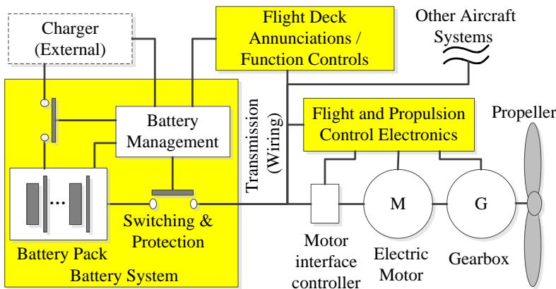 Fig. 9: Airplane Level Basic Function
The eVTOL battery system predominantly relies upon an established EV battery solution. The EV battery system attains automotive-grade performance and reliability through the incorporation of a laminated structure that enhances cooling efficiency and a robust battery management system that ensures consistent performance. Moreover, the design of the battery system, encompassing battery packs, modules, and cells, is strategically engineered to serve as protective safeguards against potential hazards from mechanical, electrical, and thermal perspectives .
The typical EV battery system consists of 3 major subsystems, including Battery Pack, Battery Management and Switching & Protection described as following:
5.1.1 BP - Battery Pack
Battery pack contains the battery modules and cells, provides the electrical energy storage capability with stable performance and reliable service. The battery pack also satisfies the remaining onboard requirements, such as environment, vibration and shock, etc.
5.1.2 SP - Switching & Protection
Switching & Protection consists of the relays, fuses for high voltage protection and the high-strength framing and packaging structure for installation and protection. The cockpit and cabin are structurally separated from high-voltage electric system during physical and electrical interface design.
The battery system case is made from steel to create a sealed structure, and the battery pack uses a robust interior of metal fixtures to secure components, which helps maintain the pack structure in case of accident or fire.
The main relay initially keeps high voltage circuit open and is activated only when control system is correct. The main relay is cut off when detecting vehicle crash. The relays work collaboratively "switching" from charging mode to discharging mode.
Fuses are deployed in the battery pack and modules to prevent high-voltage electric leakage.
5.1.3 BMS - Battery Management System
BMS performs continuous self-diagnostics by monitoring individual cell voltage, state of charge, battery temperature, battery pack hardware conditions etc. BMS optimizes conditions to provide power on demand. BMS responds to unexpected conditions by going to failsafe mode or complete shutdown depending on the circumstances; e.g. overcharging, over-temp, cell failure and crash.
5.2 Battery System FDAL allocation
The Functional Development Assurance Level (FDAL) for each of the battery system functionality are listed in the following Table 5, including the results for mapping of the function into the existing EV battery subsystems.
Table 5: FDAL for eVTOL battery System Functions
| ID# | Function | FDAL | BP | BMS | SP |
| 3.1 | Storage | ||||
| 3.1.1 | Power Storage | $B^1$ | X | ||
| 3.1.2 | storage interfaces | B | X | ||
| 3.1.3 | high-voltage Protection interface | B | X | ||
| 3.1.4 | Structural Protection | B | X | ||
| 3.2 | Generation | ||||
| 3.2.1 | manage charge | B | X | ||
| 3.2.2 | Balancing charge | A | X | ||
| 3.2.3 | leakage Protection management | A | X | ||
| 3.3. | Distribution | ||||
| 3.3.1 | power supply interfaces | A | $X^2$ | $X^2$ | |
| 3.3.2 | manage discharge | A | X | ||
| 3.3.3 | provide protection | B | X | ||
| 3.3.4 | balancing discharge | A | X | ||
| 3.4 | Situational Awareness | ||||
| 3.4.1 | monitor voltage & current | A | X | ||
| 3.4.2 | monitor temperature | A | $X^3$ | ||
| 3.4.3 | provide indication & announcement | A | X | ||
| 3.4.4 | provide data to other systems | A | X | ||
| 3.4.5 | provide thermal management | A | X | ||
| 3.4.6 | Maintain battery health & capacity | B | X | ||
According to the FDAL allocation, most of the FDAL A functions are allocated to Battery Management System, other than "provide monitor temperature" and "provide power supply interfaces to propulsion". The temperature monitor sensors and interfaces are implemented within the battery pack according to the current EV design, and the power supply interface is implemented by switching relays. The safety considerations and mitigation are as following:
-
Electric power supply interface could lead to an inadvertent power off without independent monitoring function to oversight the validation of a "power off" switch command. The "monitor" to validate the power off command for power supply interface could be implemented as part of the battery management subsystem. According to the rational for FDAL allocation in ARP 4754A, Since the BMS is a DAL A function, the DAL level of "switching & protection" function to remain as a DAL-B (and even lower) function.
-
The temperature sensors and interfaces could cause both loss and misleading information for the temperature monitor function, and subsequently lead to a thermal runaway event. It would be recommended to keep the temperature sensor simple and, in the BP, reallocate the temperature monitoring and processing software and hardware functions into BMS.
-
Further safety mitigation approach could be performed to review and update the design of the battery management function and subsystem to mitigate the safety impact at the system design level.
If the temperature processing hardware and software are implemented by BMS, both the battery pack and switching & protection consists of only simple electric and mechanical parts, which can be recognized as non-complex system. According to the pragmatic practices from civil aircraft and system development, the non-complex items may be considered as meeting IDAL A rigor when they are fully assured by a combination of testing and analysis, however requirements for these items should be validated with the rigor corresponding to the FDAL of the function .
BMS is a typical complex system embracing both electronic hardware and embedded software. It is definitely subjected to the development assurance process with the appropriated confident level of rigor to identify and correct development errors.
5.3 Development Rigor
Due to the highly complex and integrated nature of modern aircraft systems, the regulatory and industry standards have highlighted concerns about the possibility of development errors causing or contributing to aircraft Failure Conditions. Briefly speaking, a developer might introduce development errors (mistakes in requirements determination, design or implementation) which potentially cause a fault that might result in a failure. It is required to have the planned and systematic tasks used to substantiate, to an adequate level of confidence, that development errors have been identified and corrected such that the items satisfy a defined set of requirements. Therefore, a process is needed, which establishes levels of confidence that development errors that can cause or contribute to identified Failure Conditions have been minimized with an appropriate level of rigor.
The aeronautic standard ARP 4754A[4] on the other hand is highly regulated, compliance depends on government or surrogate approval, must be uniform for a class of equipment and is effectively mandatory. The automotive standard (ISO 26262) [32] is industry-driven, compliance depends on 3rd party accreditation through the supply chain, allows for different level of compliance depending on context and compliance is voluntary, at least in principle. The ISO 26262 series of standards is the adaptation of IEC 61508 [33] series of standards to address the sector specific needs of electrical and/or electronic (E/E) systems within road vehicles, and it is intended to ensure the absence of unreasonable risk due to hazards caused by malfunctioning behavior of E/E systems. The only comparable artefact of ARP 4754A to IEC 61508/ISO 26262 Systematic Capability is the concept of Item Development Assurance Level (IDAL).
Both aviation best practice recommendation and automobile standards have the similar definition and rational to address the development error with the level of rigor that the development assurance tasks performed to.
5.3.1 Rigor Modulation Definitions
a) Civil aviation definition in ARP 4754A [4]
Error: An omitted or incorrect action by a crewmember or maintenance person, or a mistake in requirements, design, or implementation (derived from AMC 25.1309).
Development Error: A mistake in requirements determination, design or implementation.
Development Assurance: All of those planned and systematic actions used to substantiate, at an adequate level of confidence, that errors in requirements, design and implementation have been identified and corrected such that the system satisfies the applicable certification basis.
Function Development Assurance Level (FDAL): The level of rigor of development assurance tasks performed to Functions. [Note: The FDAL is used to identify the ARP4754 /ED-79 objectives that need to be satisfied for the aircraft/system functions].
Item Development Assurance Level (IDAL): The level of rigor of development assurance tasks performed on Item(s). [e.g. IDAL is the appropriate Software Level in DO-178B/ED-12B, and design assurance level in DO-254/ED-80 objectives that need to be satisfied for an item].
Fault: A manifestation of an error in an item or system that may lead to a failure.
Failure: An occurrence which affects the operation of a component, part or element such that it can no longer function as intended, (this includes both loss of function and malfunction). Note: errors may cause Failures but are not considered to be Failures.
b) Automobile definition in ISO26262 [32]
Error: discrepancy between a computed, observed or measured value or condition, and the true, specified or theoretically correct value or condition. Note: An error can arise because of a fault within the system or component being considered.
Automotive Safety Integrity Level (ASIL): one of four levels to specify the item's or element's necessary ISO 26262 requirements and safety measures to apply for avoiding an unreasonable risk, with D representing the most stringent and A the least stringent level.
Fault: abnormal condition that can cause an element or an item to fail.
Failure: termination of an intended behavior of an element or an item due to a fault manifestation.
At the system level, the FDAL concept in ARP 4754A addresses the management of systematic faults (development errors). From the FDAL, it is possible to define the requirements that will build the requested confidence level. In civil aviation, the Functional Development Assurance Level (FDAL) and Item Development Assurance Level is assigned to systems and items through Level A ~ E, in which level A means rigorist level. The development assurance level is purely subjected to the severity as a quantitative analysis result.
In the automobile, Automotive System Integrity Level (ASIL) is identified by Level A ~ D, in which Level D indicates the most serious development assurance confidence. The process for ASIL generation is presented in Fig. 10, which is a subjected to quantified Risk, the production of Severity, Exposure (probability) and Controllability. The controllability factor to be considered during functional safety assessment is additional to ARP 4754A approaches.
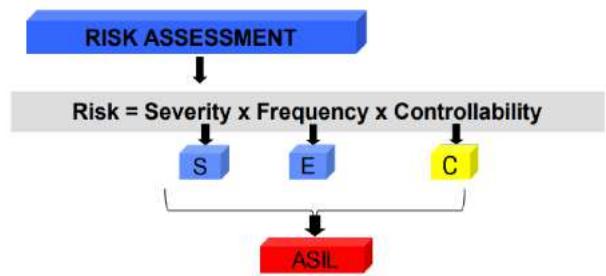 Fig. 10: ASIL, Automotive Safety Integrity Level
It includes only the satisfaction of generic objectives on the development processes. Compared to Systematic Capability, the IDAL lists few aspects of the item which could be interpreted as technical or functional requirements [35].
5.3.2 Hardware Development Rigor
Regarding for the electronic hardware development assurance indicated from IDAL defined in DO-254, there are differences in terminology which can be confusing, particularly with respect to safety levels. There are also differences in scope (ISO 26262 is primarily about safety whereas DO-254 covers a broader range of requirements), how reliability is treated (the ISO standard is more explicit here), handling validation out of context (again ISO is better here) and personnel requirements (ISO requires identified staff with training/certification) [36].
5.3.3 Software Development Rigor
When mapping the automobile software development processes defined in ISO26262 to the software certification objectives defined in DO-178B/C, a lot of gaps are identified for the integral process and certification liaison besides the basic software development activities, e.g. architecture design, coding and test etc. Detailed comparison is exhibited in Fig. 11 in the sequences of Planning, Requirements, Design, Coding, Integration and Test etc., and gaps are highlighted in yellow and red, including:
-
All Stage of Involvement (SOI) reviews and certification liaison are missed, which are mandatory for airworthiness audits and approvals.
-
Lack of the airworthiness certification plans, including certification and processes assurance plans which is required for mitigating development errors during software development.
-
The safety related requirements validation and safety assessments for derived software requirements are not required in automobile industry.
-
Lack of one level of requirements. Besides the High-Level Requirements (HLR), the Low-Level Requirements (LLR) is required for DO-178B compliance while automobile have only 1 level of the requirements.
-
The ISO26262 software development could partially match the requirements.
a) Plans for development, configuration managements, verification.
b) Standards for requirements, coding and design.
c) HLR development and attributes, coverage and traceability
It can be concluded from the process gap case study, that the existing software product developed compliance to the ISO26262 will not satisfy the rigor required by DO-178B/C is applicable to civil aviation airborne software development.
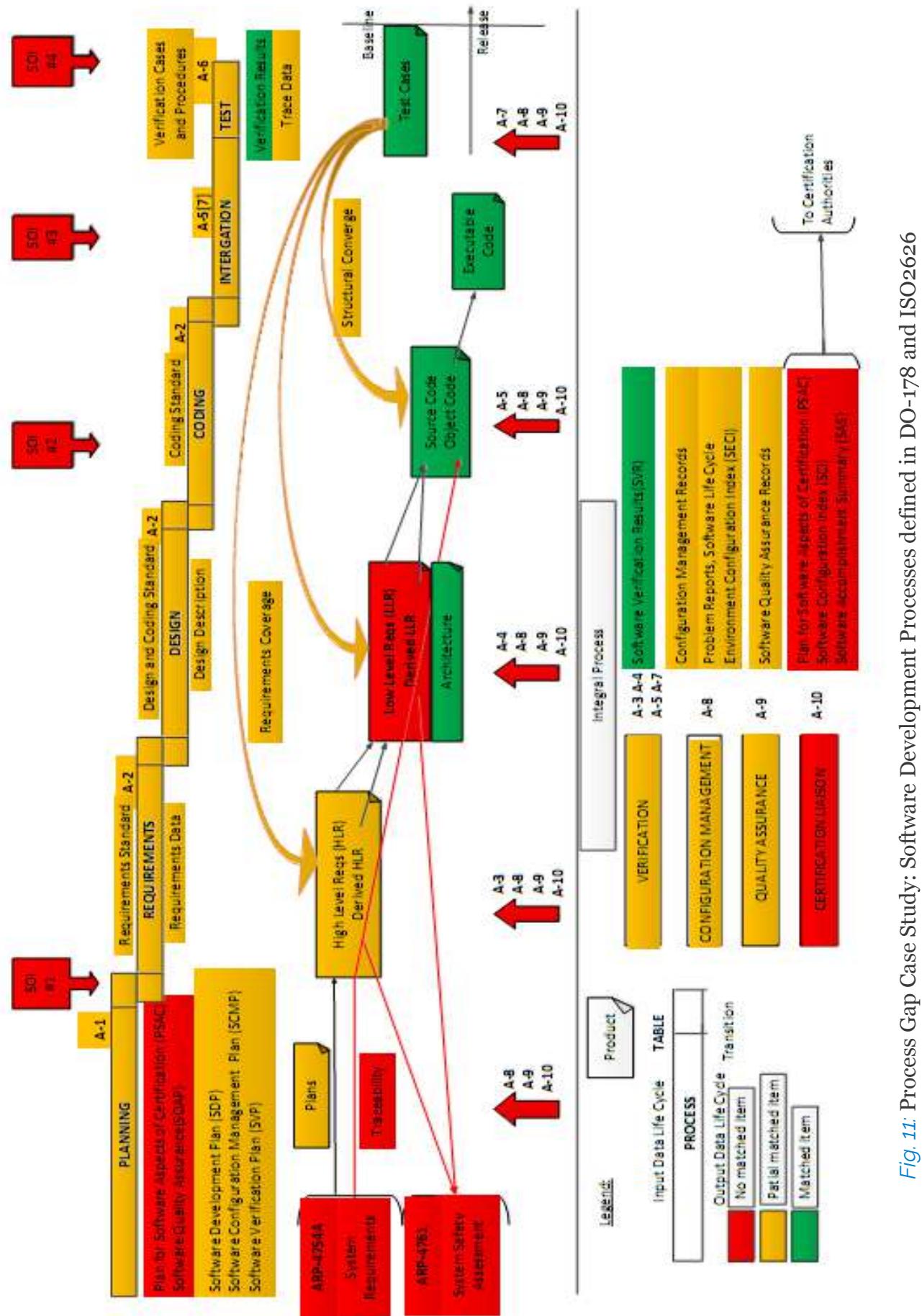 Fig. 11: Process Gap Case Study: Software Development Processes defined in DO-178 and ISO2626
IV. CONCLUSION
Even with the incorporation of well-established safety mitigation measures, specifically crashworthiness and BRS mitigations, into eVTOL aircraft, complete elimination of catastrophic failure conditions remains unattainable. Nevertheless, the analysis of safety measures at the aircraft level aids in the identification and refinement of overarching safety objectives and operational preferences.
A completeness and correctness oriented functional hierarchy of eVTOL is proposed as the foundation to proceed the FHA assessment process and the function allocation during the aircraft design phase. Leveraging the existing EV battery solutions, the aircraft power battery functionality is further decomposed and allocated into the battery systems, thereby establishing the severity classifications that defines the safety objectives for eVTOL.
To ensure compliance with airworthiness regulations, it is essential to acknowledge that no single failure or software/AEH error should lead to a Catastrophic Failure Condition. This mandate necessitates a fail-safe design for all eVTOL aircraft systems. Potential vulnerabilities and gaps associated with the application of the EV battery solution in eVTOLs encompass total power loss, thermal runaway, asymmetric power loss (partial loss), inadvertent power off, high-voltage current leakage, and the potential for misleading power supply information.
Aviation industry standards were established earlier and independently from the safety considerations for Electronics/Electric systems and programmatic components IEC 61508, leading to ISO 26262 norms as a specific instance in automobile industry. The only comparable artefact of ARP 4754A to IEC 61508/ISO 26262 Systematic Capability is the concept of Item Development Assurance Level (IDAL). It is imperative to underscore that aviation places a significantly greater and more intricate emphasis on safety considerations, encompassing software development and hardware integrity, when compared to the automotive domain. Additional attention should be paid to the FDAL allocation, system level development and safety assess process to be able to show compliance to the certification regulatory when adapting the EV battery products into eVTOL application.
The revolutionary potential of eVTOL technology to reshape our lives may remain dormant until we conquer all technical barriers and effectively address safety concerns and risks to gain public acceptance. From a business and program perspective, the strategic reuse of EV battery products during eVTOL development stands to offer substantial advantages in terms of cost and scheduling. However, it may inadvertently deviate from the fail-safe design objective, especially regarding preventing single failures or errors from triggering catastrophic failure conditions. Such deviations have the potential to introduce significant alterations and delays in the quest for airworthiness certification approvals.
Designers of eVTOL aircraft should maintain a heightened awareness of the pronounced disparities not only in functionality, interface, and performance but also in the development rigor between the aviation and automotive sectors. These disparities can have significant repercussions on both design and supply chain management. Consequently, during the development of an eVTOL aircraft, a system engineering approach and a top-down design process should be rigorously adhered to, with the aim of capturing every opportunity to leverage and improve the contemporary power battery products.
ACKNOWLEDGMENT
The research presented in this work has been supported by AVIAGE SYSTEMS. At the core of its civil avionic system solutions, AVIAGE SYSTEMS' industry leading IMA (Integrated Modular Avionics) technology provides an expandable, easily configurable, digital open-architecture computing platform, capable of hosting more functions, improving integration ability, and effectively saving operation cost. A professional chief engineering team, covering safety & RMT (Reliability, Maintainability, Testability), airworthiness certification, design quality assurance and system engineering, were established during the C919 IMA complex system design, development and certification process, expending the expertise to serve for other domains. A shorter version of this work was presented as invited keynote speech during AOPA (Aircraft Owners and Pilots Association) 1 International Forum on UAM and eVTOL (Changsha, Hunan, China, Sep 2022), SAE (Society of Automotive Engineers) Intelligent Urban Air Mobility Symposium (Shanghai, China, Oct 2022).
Conflict of Interest
The authors declare no conflict of interest.
Ethical Approval
Not applicable
Data Availability
The datasets used in this study are openly available at [repository link] and the source code is available on GitHub at [GitHub link].
Funding
This work did not receive any external funding.
References
Cite this article
Related Research



Special Issue
Launch a focused special issue to highlight research, emerging trends, and expert insights in your academic field.
